Eureka AIR delivers breakthrough ideas for toughest innovation challenges, trusted by R&D personnel around the world.

Projection display apparatus

Active Publication Date: 2017-06-01
SONY CORP
View PDF5 Cites 3 Cited by
  • Summary
  • Abstract
  • Description
  • Claims
  • Application Information

AI Technical Summary

Benefits of technology

The patent proposes an improvement to an apparatus that combines a projector and a detector for pointing operation. The proposal involves using a light valve and an illuminating unit with optical properties to reduce noise, which can affect detection. This results in improved accuracy of object detection.

Problems solved by technology

However, no touch panel is built into a screen or a wall on which images are projected, and therefore, it is necessary to detect manual operation using other means.
However, the small-sized projector itself is small in size, and it would not be stylish to operate the small-sized projector using, for example, the remote controller.
This easily results in an increase in size of a whole system.
The calibration is cumbersome because it is necessary to deal with every corner of a screen.
Therefore, such a method is not suitable for practical use.
However, because the illuminating light is turned off in the imaging, when the apparatus is used under, for example, dark external environment, it is difficult to assure sufficient brightness necessary for the imaging.
Therefore, the apparatus has restrictions in use as an apparatus that is often used under dark environment like a projector.

Method used


Image

  • Projection display apparatus
  • Projection display apparatus
  • Projection display apparatus

Examples


second modification example

2.2 Second Modification Example

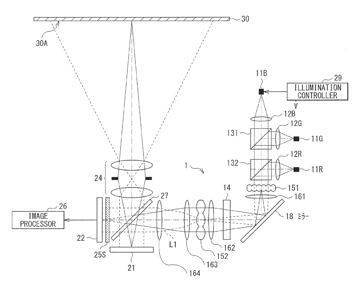
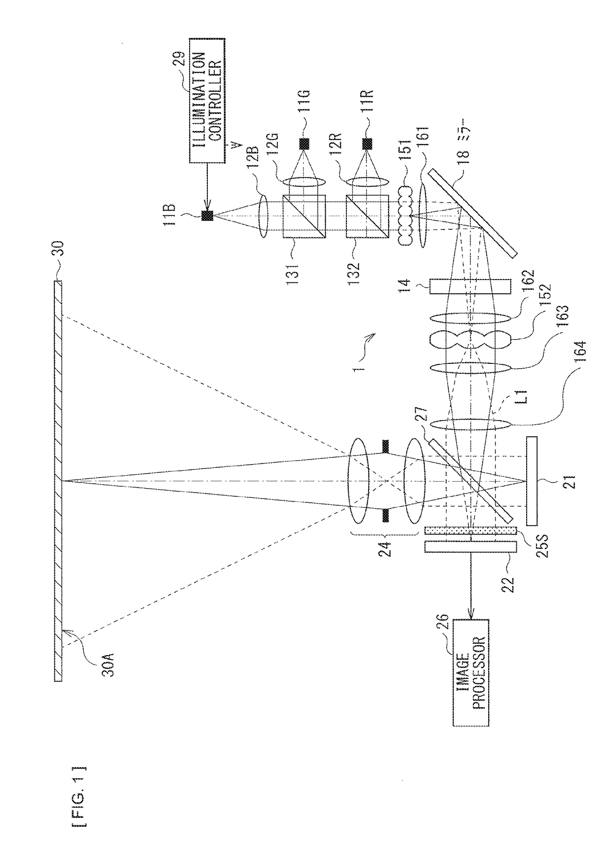
[0079]FIG. 11 illustrates a second example where the noise component is reduced, as an illuminating unit 1A according to a second modification example. FIG. 11 illustrates an example case where the green laser 11G emits the weak infrared light LIR with the wavelength of, for example, about 800 nm in addition to green light LG with a wavelength of, for example, about 520 nm. In this case, for example, the second dichroic prism 132 may have wavelength property of transmitting blue light LB and the green light LG, reflecting the red light LR, and reflecting the infrared light LIR, as illustrated in FIG. 11. As a result, the infrared light LIR may be guided toward the direction deviated from the optical path of the illuminating light L1. This keeps the infrared light LIR from being guided to the imaging device 22, which allows for the reduction in the noise component that may affect the detection light L2.

[0080]It is to be noted that the absorber 200 may b...

third modification example

2.3 Third Modification Example

[0081]FIG. 12 illustrates a third example where the noise component is reduced, as an illuminating unit 1B according to a third modification example. As with the example in FIG. 11, FIG. 12 illustrates an example case where the green laser 11G emits the weak infrared light LIR with the wavelength of, for example, about 800 nm in addition to the green light LG with the wavelength of, for example, about 520 nm. In this case, for example, the first dichroic prism 131 may have wavelength property of transmitting the blue light LB, reflecting the green light LG, and transmitting the infrared light LIR, as illustrated in FIG. 12. As a result, the infrared light LIR may be guided toward the direction deviated from the optical path of the illuminating light L1. This keeps the infrared light LIR from being guided to the imaging device 22, which allows for the reduction in the noise component that may affect the detection light L2.

fourth modification example

2.4 Fourth Modification Example

[0082]FIG. 13 illustrates a fourth example where the noise component is reduced, as an illuminating unit 1C according to a fourth modification example. FIG. 13 illustrates an example case where the blue laser 11B emits the weak infrared light LIR with the wavelength of, for example, about 800 nm in addition to the blue light LB with the wavelength of, for example, about 450 nm. In this case, for example, the first dichroic prism 131 may have wavelength property of transmitting the blue light LB, reflecting the green light LG, and reflecting the infrared light LIR, as illustrated in FIG. 13. As a result, the infrared light LIR may be guided toward the direction deviated from the optical path of the illuminating light L1. This keeps the infrared light LIR from being guided to the imaging device 22, which allows for the reduction in the noise component that may affect the detection light L2.

[0083]As an alternative configuration, although not illustrated, ...


PUM


Abstract

A projection display apparatus of the disclosure includes: a light valve (21) that modulates illuminating light (L1) on the basis of image data to output the modulated light; an illuminating unit (1) including a light source, and a plurality of optical members for illumination that generate the illuminating light (L1) on the basis of light from the light source to guide the illuminating light (L1) to the light valve (21); a projection lens (24) that projects the modulated light from the light valve (21) on a projection surface (30A), and allows detection light to enter from a direction opposite to a travelling direction of the modulated light; and an imaging device (22) that is disposed at a location optically conjugated with the light valve (21), and allows the detection light to enter through the projection lens. One or more of the plurality of optical members for illumination have optical property of reducing a noise component that affects the detection light and arises inside the illuminating unit (1).

Description

CROSS REFERENCE TO RELATED APPLICATIONS[0001]This application is a U.S. National Phase of International Patent Application No. PCT / JP2015 / 067611 filed on Jun. 18, 2015, which claims priority benefit of Japanese Patent Application No. JP 2014-153406 filed in the Japan Patent Office on Jul. 29, 2014. Each of the above-referenced applications is hereby incorporated herein by reference in its entirety.TECHNICAL FIELD[0002]The disclosure relates to a projection display apparatus having a function of detecting an object on a projection surface or in the vicinity thereof.BACKGROUND ART[0003]In recent years, in a smartphone, a tablet terminal, or any other similar mobile apparatus, the use of a touch panel has made it possible to perform page scrolling or zooming and shrinking of images being displayed on a screen through pointing operation in response to human intuition. Meanwhile, a display apparatus that displays images by projecting them on a screen has been known as a projector over th...

Claims


Application Information

Patent Timeline
IPC IPC(8): G06F3/042H04N9/31
CPCG06F3/0425H04N9/3155H04N9/3197G03B17/54G06F3/0418H04N9/3111H04N9/3164H04N9/3179H04N9/3194
Inventor MIURA, KOJI
Owner SONY CORP
Why Eureka
Eureka Blog
Learn More