
X-ray image detector

Inactive Publication Date: 2002-04-30
KK TOSHIBA
View PDF17 Cites 8 Cited by
  • Summary
  • Abstract
  • Description
  • Claims
  • Application Information

AI Technical Summary

Benefits of technology

It is accordingly the object of the present invention to provide an X-ray image detector which can reduce the size of a whole apparatus associated with an X-ray imaging tube, reduce noise components of an output X-ray image even if an incident X-ray is very weak and obtain an output image of an X-ray image of a larger area not involving an image distortion containing an adverse effect resulting from a moire, etc.

Problems solved by technology

The above-mentioned X-ray imaging tube can multiply a very weak X-ray image as an easily observable visible image and, since an electron lens is used to multiply (intensify) an X-ray image converted to a photoelectron, there arises a problem of an image distortion resulting from the electron lens.
Further, a greater space is required for the electron lens and, as a result, the size of the X-ray imaging tube becomes greater, presenting a problem.
Since, however, the proximity type electron lens cannot vary the size of an X-ray image converted to a photoelectron, it is difficult to, like the ordinary X-ray imaging tube as set out above, reduce the size of an electron image and, by doing so, enhance the energy density and improve the light strength per unit area of an output image.
In comparison with the ordinary type X-ray imaging tube as set out above, the image luminance of an output is reduced to about 1 / 10 and, for use in a medical field, an X-ray amount with which the human body has to be irradiated is increased, thus presenting a problem of increasing an amount of X-ray exposed to the human body.
61-62283, in spite of the fact that an X-ray image converted to an electric signal is a signal which is very weak in intensity, it is not multiplied until it is externally taken out and there arises a problem that more noise emerges on the output image.
5-130510, etc., it is difficult to uniform the multiplication factor of the multiplying element given to all the pixels.
This presents a problem of never improving an image quality over a whole image region.
It is possible, as reported in U.S. Pat. No. 3,394,261, to increase an image luminance of an X-ray image output by setting the MCP in the X-ray imaging tube, but in actual practice it is difficult to increase the size of the MCP.
However, a larger space is required for the electron lens, thus offering a problem not suited to a practical application.

Method used


Image

  • X-ray image detector
  • X-ray image detector
  • X-ray image detector

Examples


Embodiment Construction

With reference to the drawings, the embodiments of the present invention will be explained in more detail below.

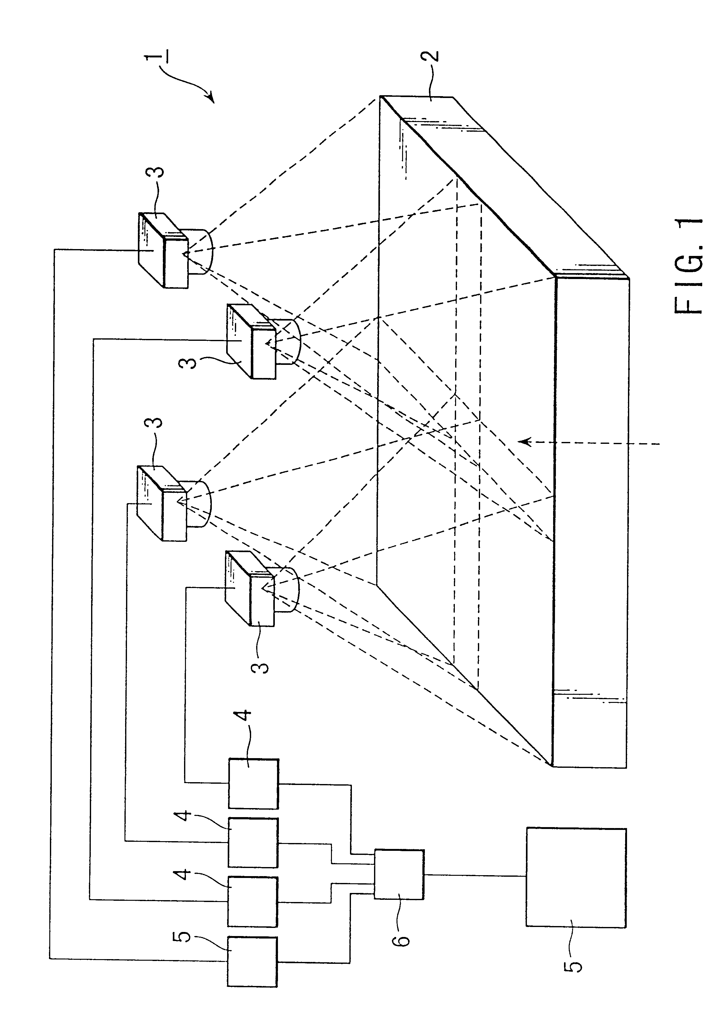
FIG. 1 is a general whole view showing a general arrangement of an X-ray image detector to which the embodiment of the present invention is applied;

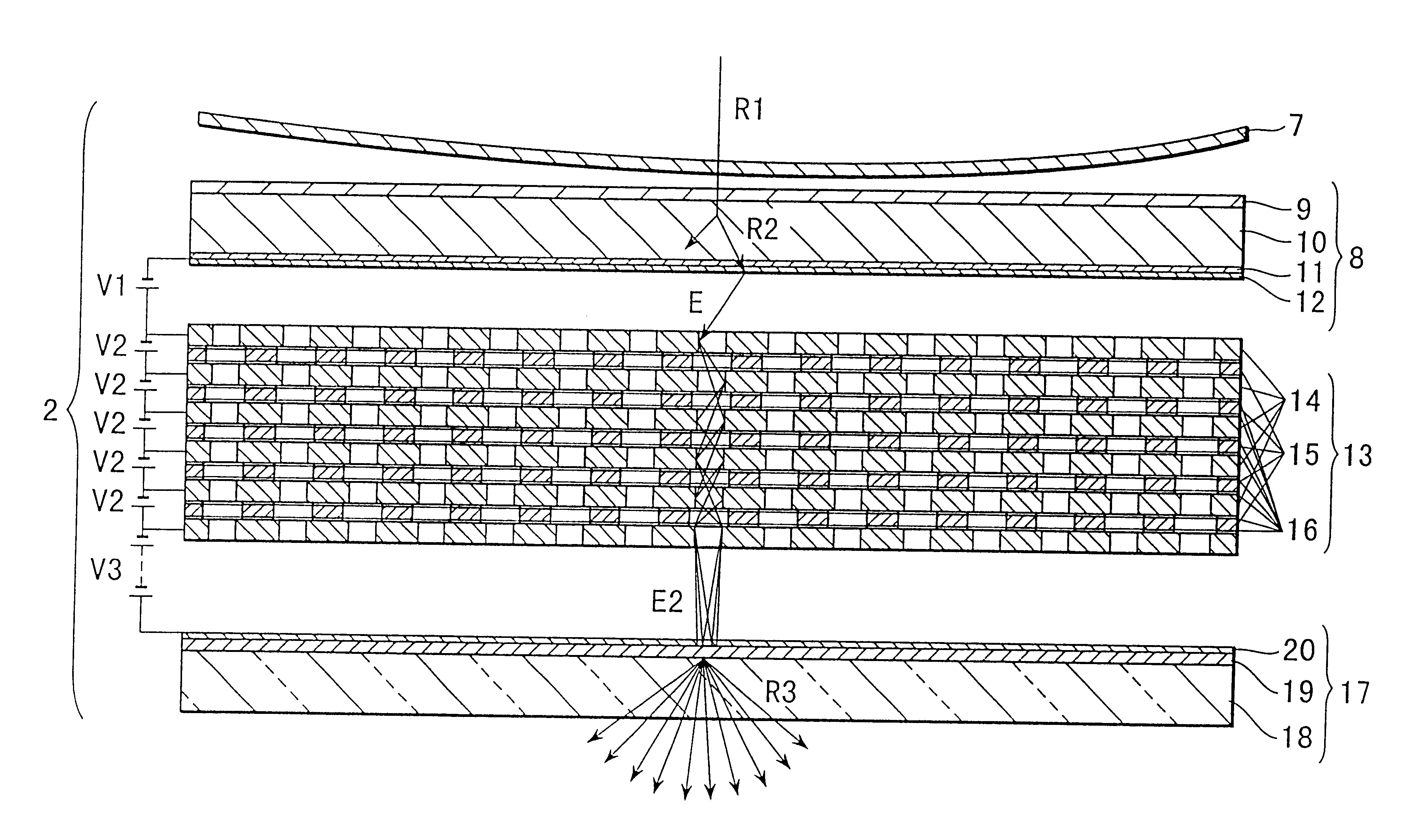
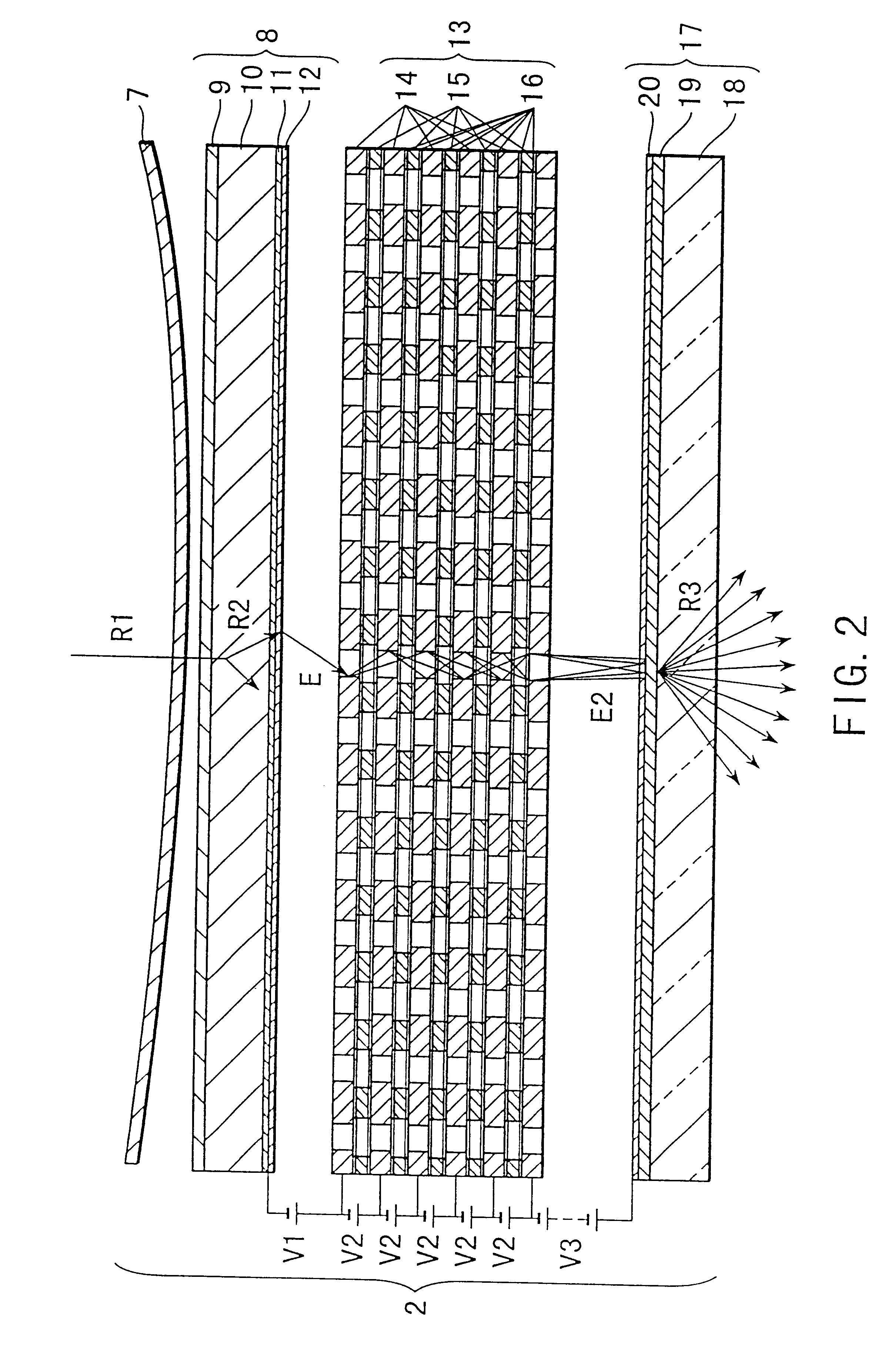
As shown in FIG. 1, the X-ray image detector 1 comprises a vacuum container 2 catching an X-ray image, that is, an X-ray passing through a to-be-detected object such as a human body and outputting a visible light image through a light-electron conversion and electron-light conversion, a plurality of image pick-up elements 3 taking, as image information, a visible light image output to an output fluorescent screen as explained at a subsequent stage with the use of FIG. 2 of the vacuum container and outputting video signals corresponding to the image information, image processing circuits 4 applying predetermined image processing to the video signals output from the respective image pick-up elements 3, and an output signal proces...


PUM


Abstract

The present invention provides an X-ray image detector (1) which can reduce the size of a whole apparatus associated with an X-ray imaging tube, reduce noise components of an output X-ray image even if an incident X-ray is very weak, and provide a distortion-free visible image or electric image. The X-ray image detector (1) comprises a vacuum container having an input fluorescent screen outputting fluorescent light, a photoelectric screen converting the fluorescent light which is output from the input fluorescent screen to a photoelectron, and an output fluorescent screen outputting a visible light image with the obtained electron, a plurality of image pick-up elements (3) arranged such that partially overlapped areas are outside an image taking area and taking the visible light image in a divided way, image processing circuits (4) so arranged as to correspond to the image pick-up elements and trimming a taken video signal, an output image processing circuit (6) obtaining a composed image and a display device (5) displaying it as one signal.

Description

The present invention relates to an X-ray image detector for converting an image which is obtained from an X-ray being a radiation to an optical or electric image signal.Generally, an X-ray is useful in the examination of an internal structure of a human body or an object and the apparatus for converting a penetration density distribution of an X-ray illuminating the human body and object, that is, the X-ray intensity distribution or X-ray image, to a visible light image or electric image signal corresponding to the X-ray have been extensively utilized.As the apparatus for converting the X-ray image to a visible light image or electric image signal, an X-ray imaging tube (X-ray image intensifying tube) and X-ray vidicon (X-ray image detector) have been developed.The X-ray imaging tube for intensifying an X-ray image signal and converting it to a visible light image comprises a vacuum container holding a vacuum therein, an input fluorescent screen arranged in the vacuum container and...

Claims


Application Information

Patent Timeline
IPC IPC(8): H01J31/50H01J31/08
CPCH01J31/506H01J31/507H01J2231/50094H01J2231/50036H01J2231/50063H01J2231/50031
Inventor AIDA, HIROSHINOJI, TAKASHI
Owner KK TOSHIBA
Learn More