Semiconductor integrated circuit

Inactive Publication Date: 2006-04-18
RAMBUS INC
View PDF10 Cites 8 Cited by
  • Summary
  • Abstract
  • Description
  • Claims
  • Application Information

AI Technical Summary

Benefits of technology

[0023]A typical means of the invention is summarized below. Every other or every few of a plurality of word lines connected to a plurality of memory cells connected to one data line are disposed to be connected to subword driver arrays arranged on the mutually opposite sides of a memory array. This disposition has an effect that, in the worst pattern of word line noise in which all the other data line pairs than the aforementioned pair to be noted read out data reverse to those of the noted pair, half of the word lines connected to receive positive noise and the other half receive negative noise, so that noise components on these word lines cancel each other on a ground level source line in the subword driver array and are thereby reduced, Similarly, in the subword driver array arranged along the other side of the memory array, half of the word lines connected to receive positive noise and the other half receive negative noise, so that noise components on these word lines cancel each other on a ground level source line in the subword driver array and are thereby reduced.

Problems solved by technology

Thus, as illustrated in FIG. 11(b), in a folded data line structure, although the coupling capacitance of the WL0 with respect to the DL0T and the DL0B may appear balanced between the C00 and the C00B, the C00 is predominantly great in a large scale integrated DRAM using small memory cells, resulting in an imbalance.
This imbalance in DL-WL coupling capacitance is a new problem which has become actualized by the decrease in the thickness of the insulating film parallel to the substrate relative to the thickness of the interlayer insulating film in the direction normal to the substrate, which in turn has resulted from the large scale integration of the DRAM.
While this WL noise is positive on one half of all the WLs of the array and negative on the other half, the alternate connection of WLs to two SWDs in the array of FIG. 13 results in the occurrence of negative noise on every WL connected to the SWDA-U and of positive noise on every WL connected to the SWDA-D.
Accordingly these noise aggregates are very great.
Furthermore, noise components having arisen on WLs take a long time to attenuate because they are not canceled until they reach the bonding pad for voltage source in the middle of the chip.
This WL noise occurring during DL amplification returns to the DLs via the WL-DL coupling capacitance, and invites erroneous actions.
Thus, in the memory array of FIG. 10 studied before this application for patent, as the WL noise components on word lines work in a direction of reinforcing one another in the sense amplifier driver SWD in the worst case, there is the problem of increased WL noise.
This deteriorates the signal read out by the sense amplifier, and accordingly destabilizes the operation of the memory.

Method used


Image

  • Semiconductor integrated circuit
  • Semiconductor integrated circuit
  • Semiconductor integrated circuit

Examples


embodiment 2

(Embodiment 2)

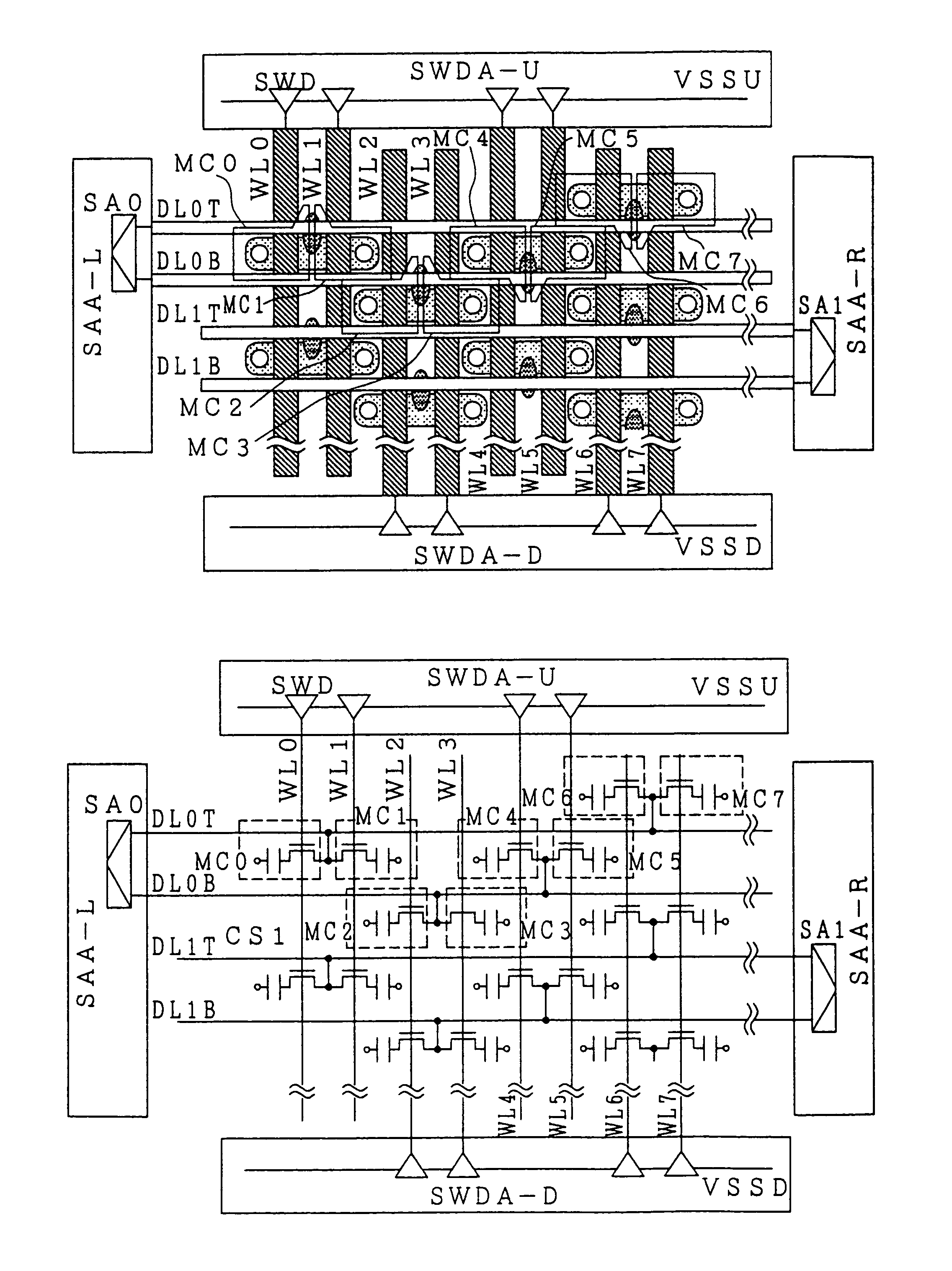
[0058]A layout and a circuit diagram of a second word line noise decreased memory array according to the invention are shown in FIG. 5. This embodiment differs from Embodiment 1 in that, on the boundaries between SWD arrays and the memory array, WLs ending at a boundary and WLs connected to an SWD array alternate each other at one line intervals.

[0059]Regarding this embodiment, too, the relationship of connection between WLs and the SWD arrays will be noted. To look at the MC0 and MC1, two mutually adjoining memory cells connected to the DL0T, they share the same DLCT, but while the WL0, out of the WLs connected to these cells, is connected to the SWDA-U, the WL1 is connected to the SWDA-D. On the other hand, to look at the MC2 and MC3, two mutually adjoining memory cells connected to the DL0B, they also share the same DLCT, but while the WL2, out of the WLs connected to these cells, is connected to the SWDA-U, the WL3 is connected to the SWDA-D. Therefore, in the layo...

embodiment 3

(Embodiment 3)

[0062]FIG. 6 illustrates a layout and a circuit diagram of a third word line noise decreased memory array according to the present invention. This embodiment differs from Embodiments 1 and 2 in that in that, on the boundaries between SWD arrays and the memory array, WLs connected to an SWD array and WLs ending at a boundary alternate each other at four line intervals.

[0063]Regarding this embodiment, too, the relationship of connection between WLs and the SWD arrays will be noted. Both the WL0 and WL1 connected to the MC0 and MC1, two mutually adjoining memory cells connected to the DL0T, are connected to the SWDA-U. On the other hand, both the WL2 and WL3 connected to the MC2 and MC3, two mutually adjoining memory cells connected to the DL0B, are also connected to the SWDA-U. Therefore, in this embodiment, noise components arising on the WL0 and WL1 are canceled on the VSSU by those arising on the WL2 and WL3. Similarly, noise components arising on the WL4 and WL5 are ...

embodiment 4

(Embodiment 4)

[0066]FIG. 7 illustrates a layout and a circuit diagram of a fourth word line noise decreased memory array according to the invention. This embodiment, though its boundaries between the SWD arrays and the memory array are similar to those shown in FIG. 11, differs from Embodiments 1, 2 and 3 in that the directions of the data line contacts DLCTs of the MC4, MC5, MC6 and MC7 in the memory cell array are altered so that memory cells whose diffused layers are aligned in the DL direction are connected alternately to different DLs.

[0067]Both the WL0 and WL1 connected to the MC0 and MC1, two mutually adjoining memory cells connected to the DL0T, are connected to the SWDA-U. On the other hand, both the WL2 and WL3 connected to the MC2 and MC3, two mutually adjoining memory cells connected to the DL0B, are also connected to the SWDA-U. Therefore, in this embodiment, noise components arising on the WL0 and WL1 are canceled on the VSSU by those arising on the WL2 and WL3. The tw...


PUM


Abstract

In a large scale integrated DRAM in pursuit of micro fabrication, data line-word line coupling capacitances are unbalanced between paired data lines. A data line-word line imbalance generates large noise when the data lines are subjected to amplification, which is highly likely to invite deterioration of very small signals on the data lines and erroneous amplification of data. One or a few of a plurality of word lines connected to a plurality of memory cells connected to one data line are alternately connected to subword driver arrays arranged on the opposing sides of a memory array. Positive and negative word line noise components cancel each other in the subword drivers when the data lines are subjected to amplification, so that the word line noise can be reduced. Therefore, signals read out by sense amplifiers can be prevented from deterioration thereby to increase the reliability of memory operation.

Description

[0001]This is a continuation application of U.S. Ser. No. 10 / 155,085, filed May 28, 2002 U.S. Pat. No. 6,625,051; which is a continuation application of U.S. Ser. No. 09 / 923,542, filed Aug. 8, 2001, now U.S. Pat. No. 6,426,889; which is a continuation application of U.S. Ser. No. 09 / 532,734, filed Mar. 22, 2000, now U.S. Pat. No. 6,278,628.FIELD OF THE INVENTION[0002]The present invention relates to reduction of memory array noise in a semiconductor apparatus involving a memory array or arrays.BACKGROUND OF THE INVENTION[0003]The items of literature referenced in this specification are listed below, and they will be referenced by reference number. [Reference 1]: ITOH, K., Very Large Scale Integrated Memories, Baifukan, Nov. 5, 1994 (1st edition), pp. 214–217, and [Reference 2]: K. Itoh, IEEE Journal of Solid State Circuit, Vol. 25, No. 3, (1990); pp. 778–789 ([Reference 2] is the original work referenced in [Reference 1]).[0004][Reference 1] discusses noise arising via word lines wh...

Claims


Application Information

Patent Timeline
IPC IPC(8): H01L27/108G11C11/407G01R31/28G11C5/06G11C8/14G11C11/401G11C11/4096G11C11/4097H01L21/8242
CPCG11C5/06G11C5/063G11C7/02G11C8/08G11C8/14H01L27/10882G11C11/4085G11C11/4096G11C11/4097H01L27/0207G11C11/408H01L27/10814H10B12/315H10B12/48G11C5/025G11C7/06G11C11/4091
Inventor SEKIGUCHI, TOMONORITAKEMURA, RIICHIROKAJIGAYA, KAZUHIKOKIMURA, KATSUTAKATAKAHASHI, TSUGIO
Owner RAMBUS INC
Why Eureka
Try Eureka