Liquid crystal grating coupling

Inactive Publication Date: 2006-01-26
SIOPTICAL INC +1
View PDF8 Cites 28 Cited by
  • Summary
  • Abstract
  • Description
  • Claims
  • Application Information

AI Technical Summary

Benefits of technology

[0010] The need remaining in the prior art is addressed by the present invention, which relates to a liquid crystal/grating coupling arrangement and, more particularly, to a particular l

Problems solved by technology

One issue associated with the use of opto-electronic integrated circuits is the problem of coupling light into and out of a planar waveguide structure, particularly when using a relatively thin (e.g., sub-micron thickness) waveguiding layer.
Moreover, the grating structure of Rigrod is found to be limited to diffracting a first-order mode of the light beam and is generally used for steering a particular wavelength input signal.
As a result, the Rigrod structure remains incapable of efficiently coupling a relatively large range of wavelengths into a relatively thin surface waveguide layer.
The ability to couple a free space optical signal into and out of a planar waveguiding layer on a silicon substrate (particularly a sub-micron thick waveguiding layer) is a problem that is of current research.
While these coupling methods are relatively wavelength-insensitive, the insertion los

Method used


Image

  • Liquid crystal grating coupling
  • Liquid crystal grating coupling
  • Liquid crystal grating coupling

Examples


Embodiment Construction

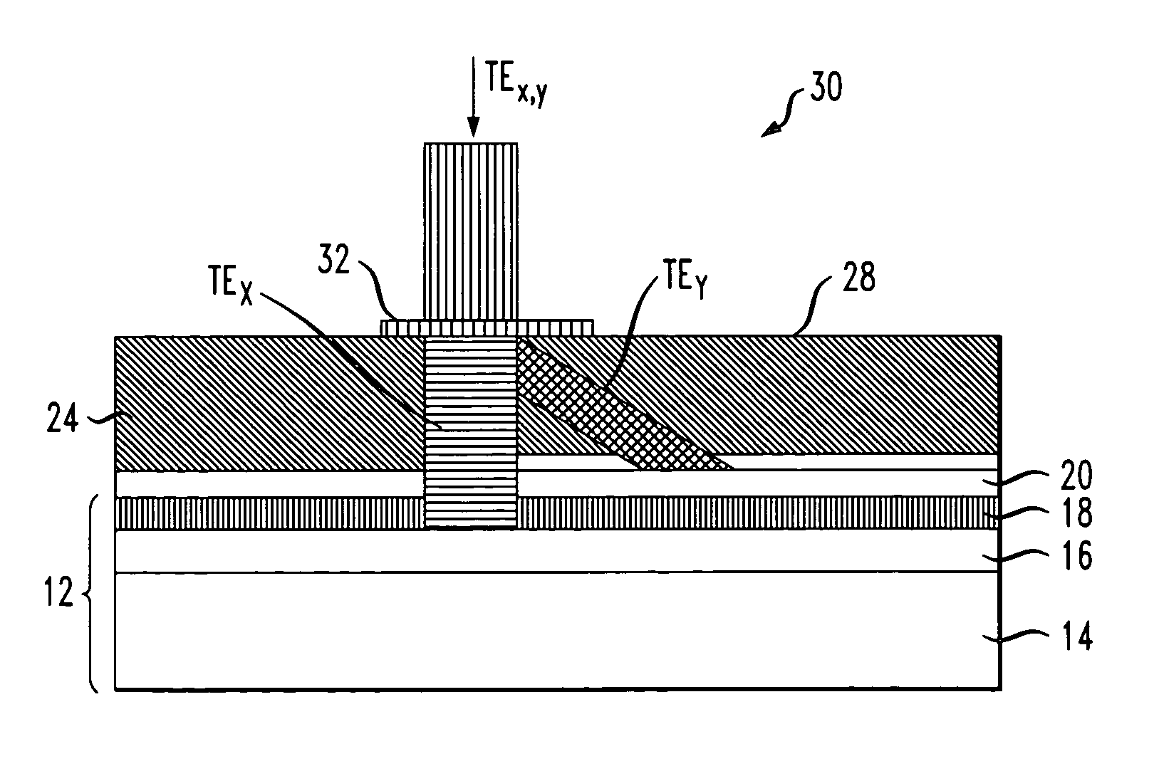
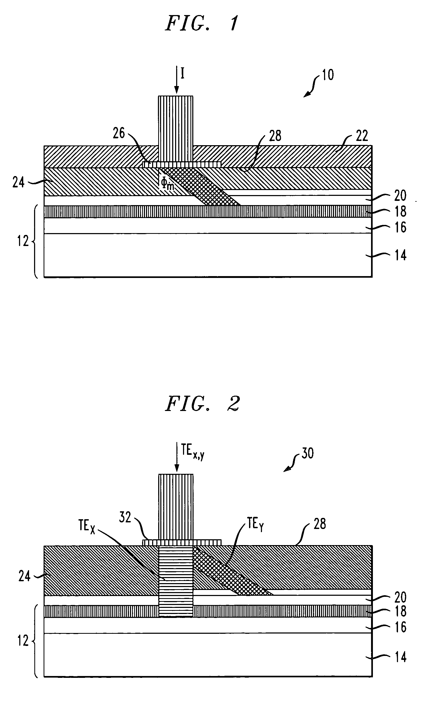
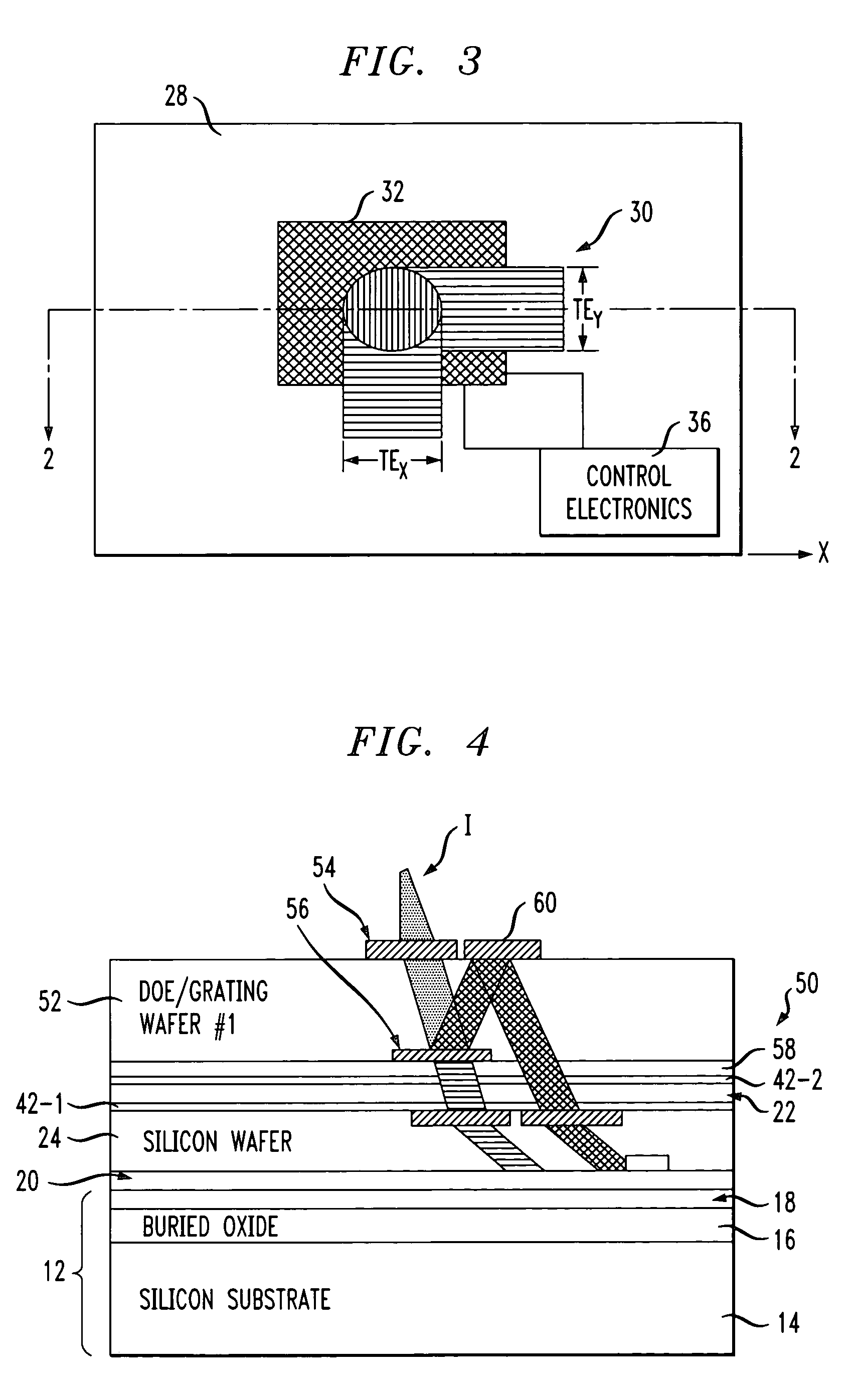
[0022] Materials classified as liquid crystals are typically liquid at high temperatures and solid at low temperatures, but in the intermediate temperature range they display properties of both. The essential feature of a liquid crystal is the long, rod-like molecular structure. The molecules will align in the presence of an electric field, where the alignment is the result of the anisotropic dielectric constant (refractive index) characteristic of liquid crystals. In accordance with the present invention, these attributes of liquid crystals are capitalized on to provide an input / output coupling arrangement that is “tunable” so as to accommodate for different input wavelengths, different incident angles, and the like.

[0023] In particular, most liquid crystal materials exhibit a refractive index in the range of 1.3 to 2.0. It has been found that a change in the index value on the order of 0.2 (i.e., Δn=0.2) will correspond to providing a coupling angle control on the order of 6.5°. ...


PUM


Abstract

A tunable optical coupling arrangement for use with a relatively thin (generally sub-micron thickness) silicon waveguiding layer of a silicon-on-insulator (SOI) substrate. The arrangement comprises a multi-layer structure including a substrate for supporting one or more diffractive optical elements and a layer of tunable liquid crystal material. The multi-layer structure is disposed over a conventional SOI substrate including the thin silicon waveguiding layer, where the refractive index of the liquid crystal material can be modified to adjust the deflection of an input optical beam through the various diffractive optical elements and present an optimized launch angle into the silicon waveguiding layer, thus reducing insertion loss at the waveguiding layer.

Description

CROSS-REFERENCE TO RELATED APPLICATION [0001] This application claims the benefit of Provisional Application No. 60 / 590,619, filed Jul. 23, 2004.TECHNICAL FIELD [0002] The present invention relates to a liquid crystal / grating coupling arrangement and, more particularly, to a tunable liquid crystal / grating arrangement for use in coupling free space optical signals into and out of a relatively thin SOI waveguiding layer of an SOI-based opto-electronic device structure. BACKGROUND OF THE INVENTION [0003] To meet the bandwidth requirements of current and future high speed communication applications, state-of-the-art telecommunication components and systems must provide a host of sophisticated signal processing and routing functions, in both the optical and electronic domains. As the complexity level increases, the integration of more functions and components within a single package becomes strategic in terms of meeting various system-level requirements, while also reducing the associate...

Claims


Application Information

Patent Timeline
IPC IPC(8): G02B6/26
CPCG02B6/2852G02F2201/302G02F2001/0144G02F1/2955G02F1/0144
Inventor PIEDE, DAVIDGOTHOSKAR, PRAKASHWAGNER, HARVEYGHIRON, MARGARET
Owner SIOPTICAL INC
Why Eureka
Try Eureka