
Optical transmission apparatus using duobinary modulation

a transmission apparatus and duobinary technology, applied in the field of optical transmission apparatuses, can solve the problem of more time jitters of signals in optical duobinary signals, and achieve the effect of minimizing the pattern dependence of duobinary signals

Inactive Publication Date: 2006-01-26
SAMSUNG ELECTRONICS CO LTD
View PDF7 Cites 13 Cited by
  • Summary
  • Abstract
  • Description
  • Claims
  • Application Information

AI Technical Summary

Benefits of technology

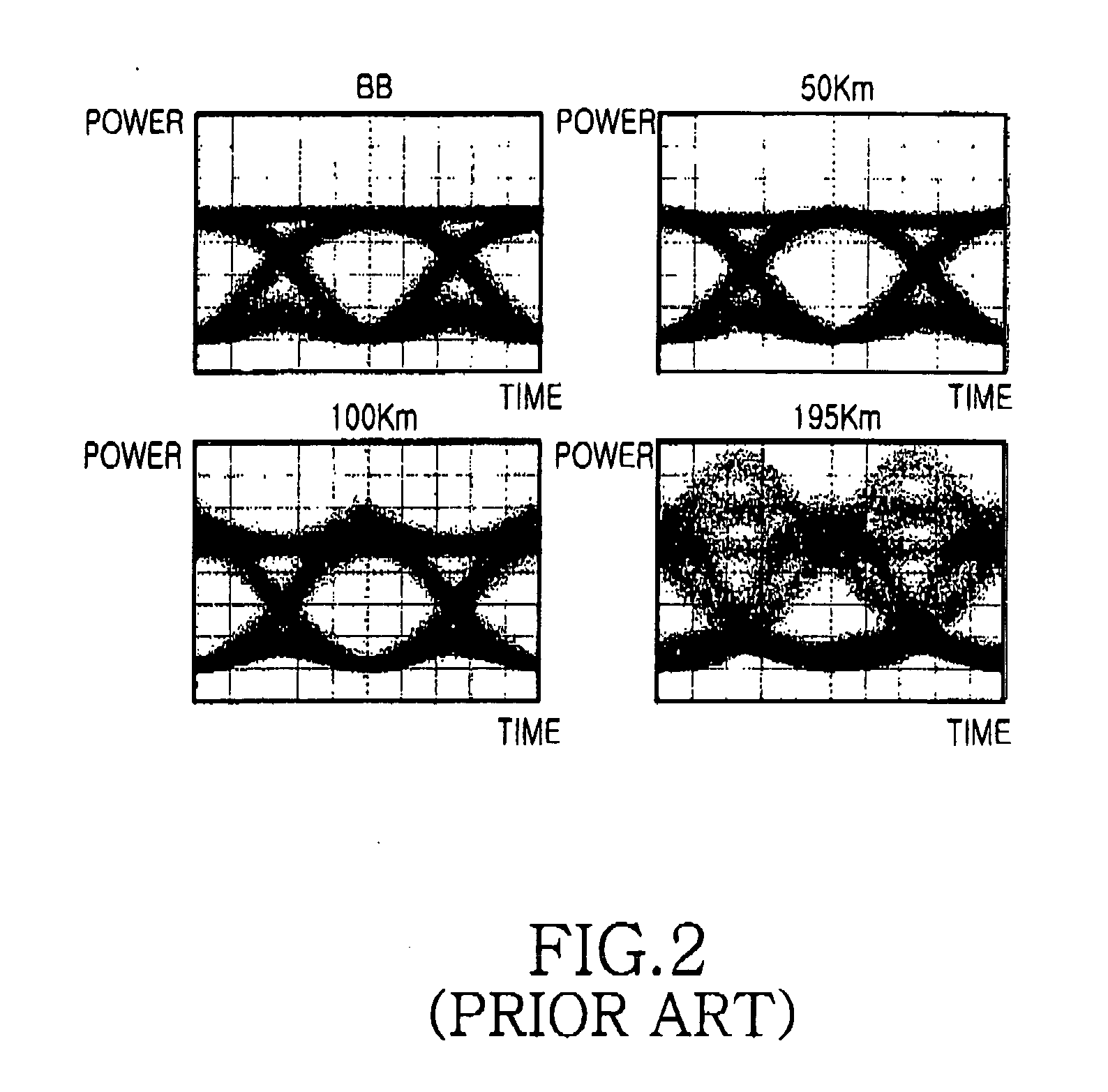
[0011] Another aspect of the present invention relates to an optical transmission apparatus using duobinary modulation capable of minimizing pattern dependence of duobinary signals, which is caused when an electrical low bandpass filter is not used.

Problems solved by technology

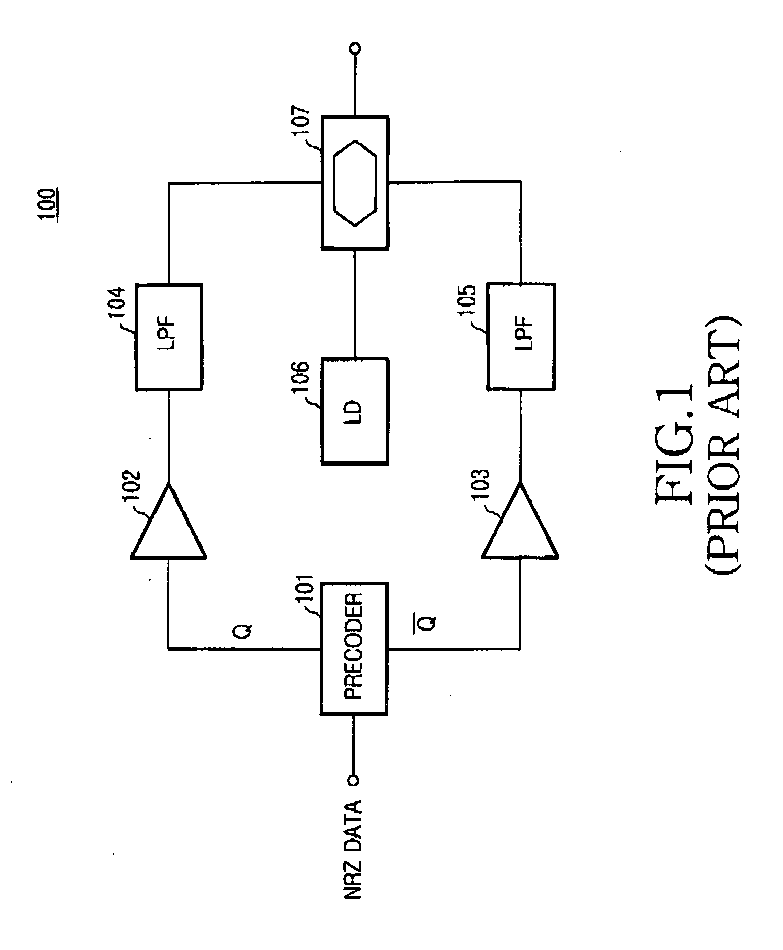
Also, the conventional apparatus has disadvantages in that time jitters of signals occur more in the optical duobinary signals than in general NRZ signals due to non-ideal characteristics of the electrical low bandpass filter.

Method used


Image

  • Optical transmission apparatus using duobinary modulation
  • Optical transmission apparatus using duobinary modulation
  • Optical transmission apparatus using duobinary modulation

Examples


Embodiment Construction

[0026] Now, embodiments of the present invention will be described in detail with reference to the annexed drawings. In the drawings, the same or similar elements are denoted by the same reference numerals even though they are depicted in different drawings. In the following description, a detailed description of known functions and configurations incorporated herein will be omitted when it may obscure the subject matter of the present invention. Also, the terms used in the following description are terms defined taking into consideration the functions obtained in accordance with the embodiments of the present invention.

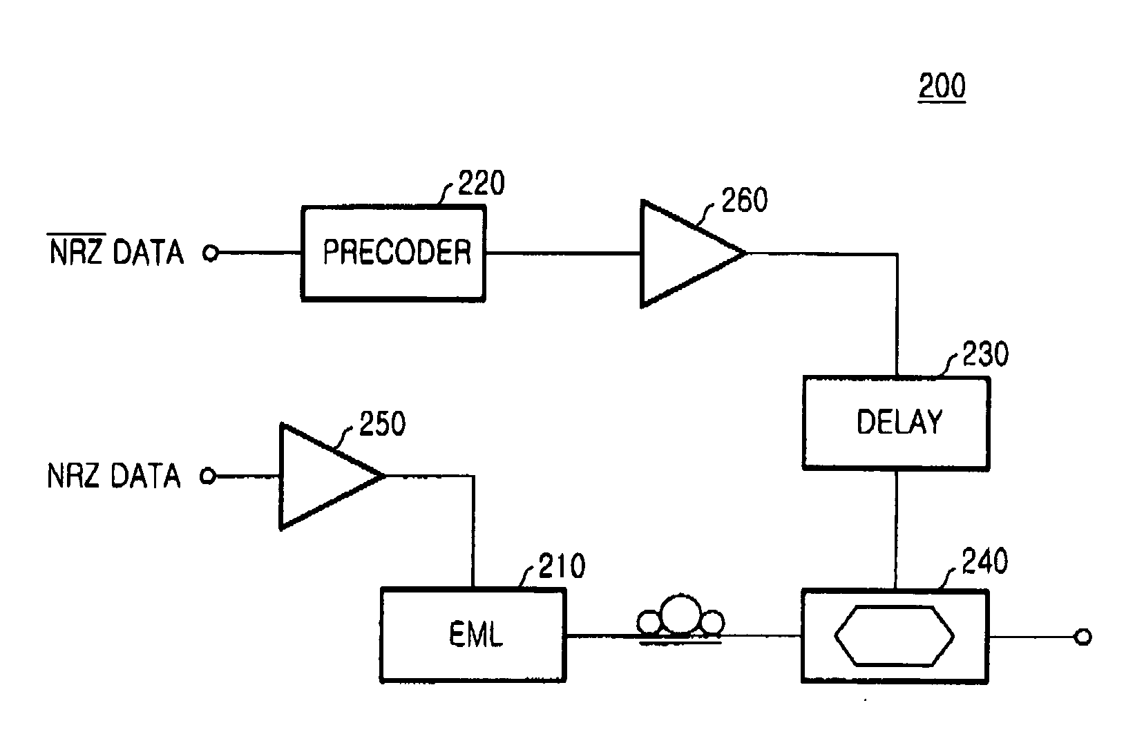
[0027]FIG. 3 is a block diagram illustrating an optical transmission apparatus 200 using duobinary modulation according to one embodiment of the present invention.

[0028] With reference to FIG. 3, the optical transmission apparatus 200 includes an EML (Electro-absorption Modulated Laser) 210, a precoder 220, a time delay 230, and an optical modulator 240. The appara...


PUM


Abstract

An optical transmission apparatus using duobinary modulation adapted to an optical communication system using dense wavelength division multiplexing (DWDM) is disclosed. The duo-binary optical transmission apparatus includes an electro-absorption modulated laser (EML) for performing a light intensity modulation operation based on an electrical data signal and producing a modulated optical signal, the EML having a light source for outputting carriers and a modulator for performing the light intensity modulation operation, a precoder for inputting an inverted signal of the electrical data signal and encoding it to an encoded signal, and a modulator for performing a phase modulation of the optical signal modulated by the EML and outputting a duo-binary optical signal, according to the encoded signal.

Description

CLAIM OF PRIORITY [0001] This application claims priority to an application entitled “OPTICAL TRANSMISSION APPARATUS USING DUOBINARY MODULATION,” filed in the Korean Intellectual Property Office on Jul. 20, 2004 assigned Serial No. 2004-56305, the contents of which are hereby incorporated by reference. BACKGROUND OF THE INVENTION [0002] 1. Field of the Invention [0003] The present invention relates to an optical transmission apparatus, and more particularly to an optical transmission apparatus using duobinary modulation adapted to an optical communication system using dense wavelength division multiplexing (DWDM). [0004] 2. Description of the Related Art [0005] Duobinary modulation converts a binary signal into a ternary signal or multi-level signal, in which the phase of the binary signal is inverted at a digit ‘0’. Since a duo-binary signal requires a relatively narrow line width as compared to an OOK (On-Off Keying) signal with respect to optical spectrum, it beneficially reduces...

Claims


Application Information

Patent Timeline
IPC IPC(8): H04B10/04H04B10/12G02F1/015H04B10/2507G02F1/03H04B10/2513H04B10/516H04B10/61H04J14/00H04J14/02
CPCH04B10/505H04B10/5167H04B10/5055H04B10/50H04B10/516H04B10/25
Inventor LEE, HAN-LIMKIM, HOONLEE, JAE-HOONOH, YUN-JEHWANG, SEONG-TAEK
Owner SAMSUNG ELECTRONICS CO LTD
Learn More