Electrically variable transmission with selective fixed ratio operation
Inactive Publication Date: 2006-01-26
GM GLOBAL TECH OPERATIONS LLC
View PDF5 Cites 74 Cited by
Summary
Abstract
Description
Claims
Application Information
AI Technical Summary
This helps you quickly interpret patents by identifying the three key elements:
Problems solved by technology
Method used
Benefits of technology
Benefits of technology
[0016] The present invention improves upon the above-referenced prior art transmissions by providing one or more additional clutches to enhance operation of the transmission, to allow additional fixed speed ratios and to allow an additional compound-power-split speed ratio range. An object of the invention is to provide the best possible energy efficiency and emissions for a given engine. In addition, optimal performance, capacity, package size, and ratio coverage for the transmission are sought.
[0017] A fixed speed ratio is an operating condition in which the mechanical power input to the transmission is transmitted mechanically to output, and no power flow is necessary through the motor / generators. An electrically variable transmission that may selectively achieve several fixed speed ratios for operation near full engine power can be smaller and lighter for a given maximum capacity. Fixed ratio operation may also result in lower fuel consumption when operating under conditions where engine speed can approach its optimum without using the motor / generators.
[0018] In comparison to prior art electrically variable transmissions with only one clutch for each of two speed ranges (C1 and C2), this invention reduces power flow through the electrical path, reducing electrical component costs and power losses. By providing a third clutch (C3), one of the motors can thereby be locked to the transmission case to provide, along with the application of C2, an additional fixed speed ratio to allow high speed cruising with improved transmission efficiency.
Problems solved by technology
Fixed ratio operation may also result in lower fuel consumption when operating under conditions where engine speed can approach its optimum without using the motor / generators.
Method used
Image
Click on the blue label to locate the original text in one second.
Reading with bidirectional positioning of images and text.
Examples
second exemplary embodiment
Description of a Second Exemplary Embodiment
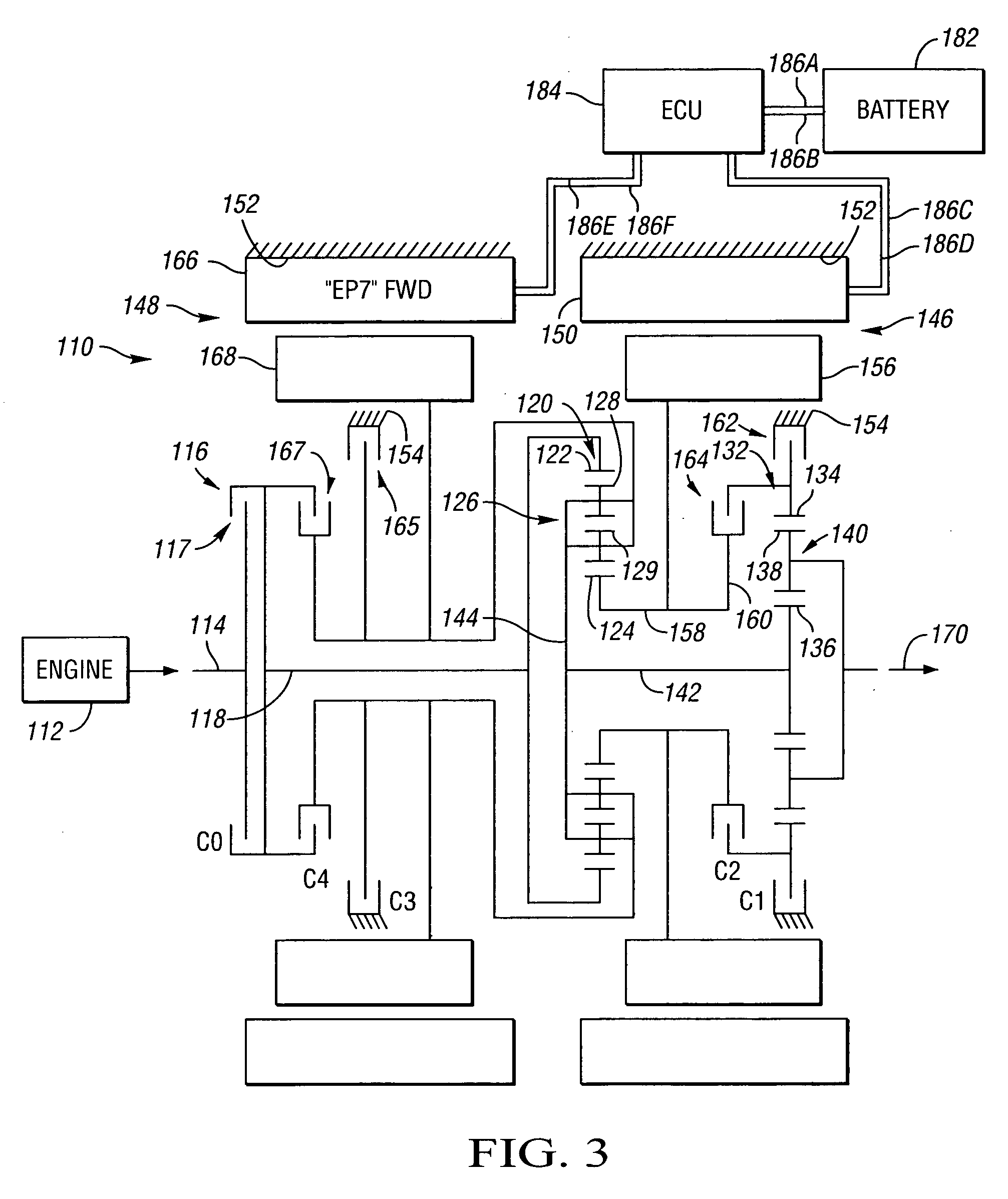
[0085] With particular reference to FIG. 3, another preferred embodiment of the improved electrically variable transmission is identified generally by the designation 110. The operating components of FIG. 3 are substantially similar to those of FIG. 1, so like reference numerals are used to refer to like components from FIGS. 1 and 3. In FIG. 3, the transmission of FIG. 1 has been rearranged in a rear wheel drivelayout. It includes four torque transfer devices, as in FIG. 1, and operates in accordance with the chart of FIG. 2.
[0086] The transmission 110 of FIG. 4 may, in part, receive its input power from an engine 112. In the embodiment depicted the engine 112 may also be a fossil fuel engine, such as a diesel engine which is readily adapted to provide its available power output typically delivered at a constant number of revolutions per minute (RPM). As shown, the engine 112 has an output shaft 114 that may also serve as the forward in...
third exemplary embodiment
Description of a Third Exemplary Embodiment
[0099] Turning to FIG. 4, a transmission 210 is shown in accordance with a third exemplary embodiment of the invention. This transmission is functionally and structurally similar to the transmissions 10 and 110 of FIGS. 1 and 3, except that a fifth clutch is added.
[0100] As shown, the transmission 210 includes an input member 218 which receives power from the engine 212 and delivers the power to the first planetary gear set 220 via the ring gear member 222.
[0101] The transmission 210 utilizes two planetary gear sets. The first is a compound planetary gear set 220 that employs the outer gear member 222, typically designated as the ring gear. The ring gear 222 also circumscribes an inner gear member 224, typically designated as the sun gear. The carrier assembly 226, in the planetary gear set 220, however, rotatably supports two sets of planet gears 228 and 229. Each of the plurality of planet gears 229 simultaneously, and meshingly, engage...
fourth exemplary embodiment
Description of a Fourth Exemplary Embodiment
[0117] In yet another embodiment, the transmission 210 of FIG. 4 could be modified by eliminating the clutch 265 (C3), and relocating the clutch 267 (C4) so that it selectively connects the rotor 256 with the carrier 226, while still providing input split, compound split and output split modes of operation. In this configuration, series hybrid operation (S1) is achieved with the engagement of clutches 262 (C1) and 267(C4). Variable ratio mode operation (V1) is achieved with the engagement of clutches 262 (C1) and 268 (C5). A first fixed ratio is achieved in fixed gear (F1) with clutches 262, 267 and 268 engaged. A second fixed ratio is achieved in fixed gear (F2) with clutches 262, 264 and 268 engaged. A third fixed ratio is achieved in fixed gear (F3) with clutches 264, 267 and 268 engaged. In variable ratio mode (V2), clutches 264 and 268 are engaged to provide electrically variable ratios in a compound split mode. An output split range ...
PUM
Abstract
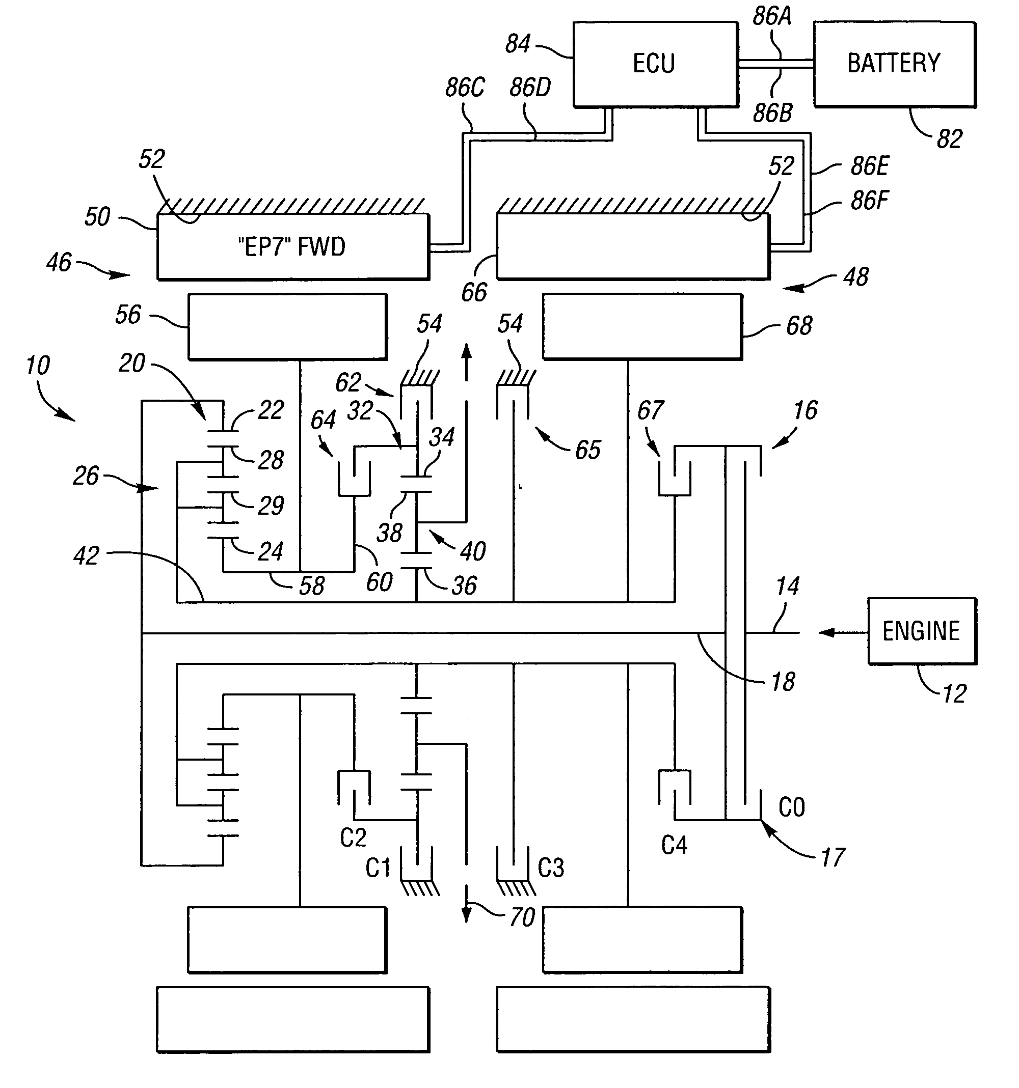
An electrically variable transmission includes: an input member to receive power from an engine; an output member; first and second motor / generators; and first and second differentially geared planetary gear sets each having first, second and third gear members. The input member is continuously connected to the first member of the first planetary gear set, and the output member is continuously connected to the first member of the second planetary gear set. The first motor / generator is continuously connected to the second member of the first planetary gear set, and selectively connected to the second member of the second planetary gear set. The second motor / generator is continuously connected with the third member of the second planetary gear set. A first torque transfer device selectively grounds the second member of the second planetary gear set. A second torque transfer device selectively connects the second member of the second planetary gear set to the second member of the first planetary gear set. An optional third torque transfer device selectively grounds the third member of the first planetary gear set. An optional fourth torque transfer device selectively connects at least two of the members together such that all members of the first planetary gear set rotate together at the same speed. An optional fifth torque transfer device selectively connects the third member of the first planetary gear set with the third member of the second planetary gear set.
Description
CROSS-REFERENCE TO RELATED APPLICATION [0001] This application claims the benefit of U.S. Provisional Application No. 60 / 590,427, filed Jul. 22, 2004, which is hereby incorporated by reference in its entirety.TECHNICAL FIELD [0002] The present invention relates to a transmission that may be selectively operated in an input-split speed ratio range and in one or two compound-split speed ratio ranges, and in two, three or four fixed speed ratios. The present invention also relates to a transmission having two gearing components, typically planetary gear sets, that may selectively be used for differential gearing, and three, four or five clutches in the nature of torque transfer devices. BACKGROUND OF THE INVENTION [0003] Internal combustion engines, particularly those of the reciprocating piston type, currently propel most vehicles. Such engines are relatively efficient, compact, lightweight, and inexpensive mechanisms by which to convert highly concentrated energy in the form of fuel ...
Claims
Application Information
Patent Timeline
Application Date:The date an application was filed.
Publication Date:The date a patent or application was officially published.
First Publication Date:The earliest publication date of a patent with the same application number.
Issue Date:Publication date of the patent grant document.
PCT Entry Date:The Entry date of PCT National Phase.
Estimated Expiry Date:The statutory expiry date of a patent right according to the Patent Law, and it is the longest term of protection that the patent right can achieve without the termination of the patent right due to other reasons(Term extension factor has been taken into account ).
Invalid Date:Actual expiry date is based on effective date or publication date of legal transaction data of invalid patent.

