LED lamp for light source of lighting device

a technology of led lamps and light sources, applied in the field of led lamps, can solve the problems of increased product cost, reduced product yield, complicated work operation, etc., and achieve the effects of high luminance, small area, and high luminan

Inactive Publication Date: 2006-02-02
STANLEY ELECTRIC CO LTD
View PDF25 Cites 59 Cited by
  • Summary
  • Abstract
  • Description
  • Claims
  • Application Information

AI Technical Summary

Benefits of technology

[0020] If a plurality of LED chips are used, light from the plurality of LED chips is not diffused into a large area. The light heads in the direction of a lens as parallel rays with a small area and high luminance, and passes through the lens. Accordingly, if a lens cut is formed in the lens to properly diffuse the light in a horizontal direction, it is possible to obtain the desired light distribution characteristics. Also, it is possible to obtain an epoch-making effect that the LED lamp can compose a headlight which can radiate a light beam with high luminance to a distant place.

Problems solved by technology

Accordingly, actual attachment requires high precision, and hence work operation becomes complicated and product yield is reduced.
As a result, there is a problem in that costs are increased for the product.
It is difficult and almost impossible, however, to precisely orient light from the individual LEDs in a desired direction, so that it is also difficult or impossible to obtain a sufficient amount of light for brightly lighting up a distant location.
As a lighting device such as a headlight, however, lighting at an attainable distance is insufficient even if the desired light distribution characteristic is obtained.
Therefore, the LED lighting device is not commonly available in a headlight.
However, demand for a solid state light source is strong in recent years due to their low maintenance characteristics.

Method used


Image

  • LED lamp for light source of lighting device
  • LED lamp for light source of lighting device
  • LED lamp for light source of lighting device

Examples


Embodiment Construction

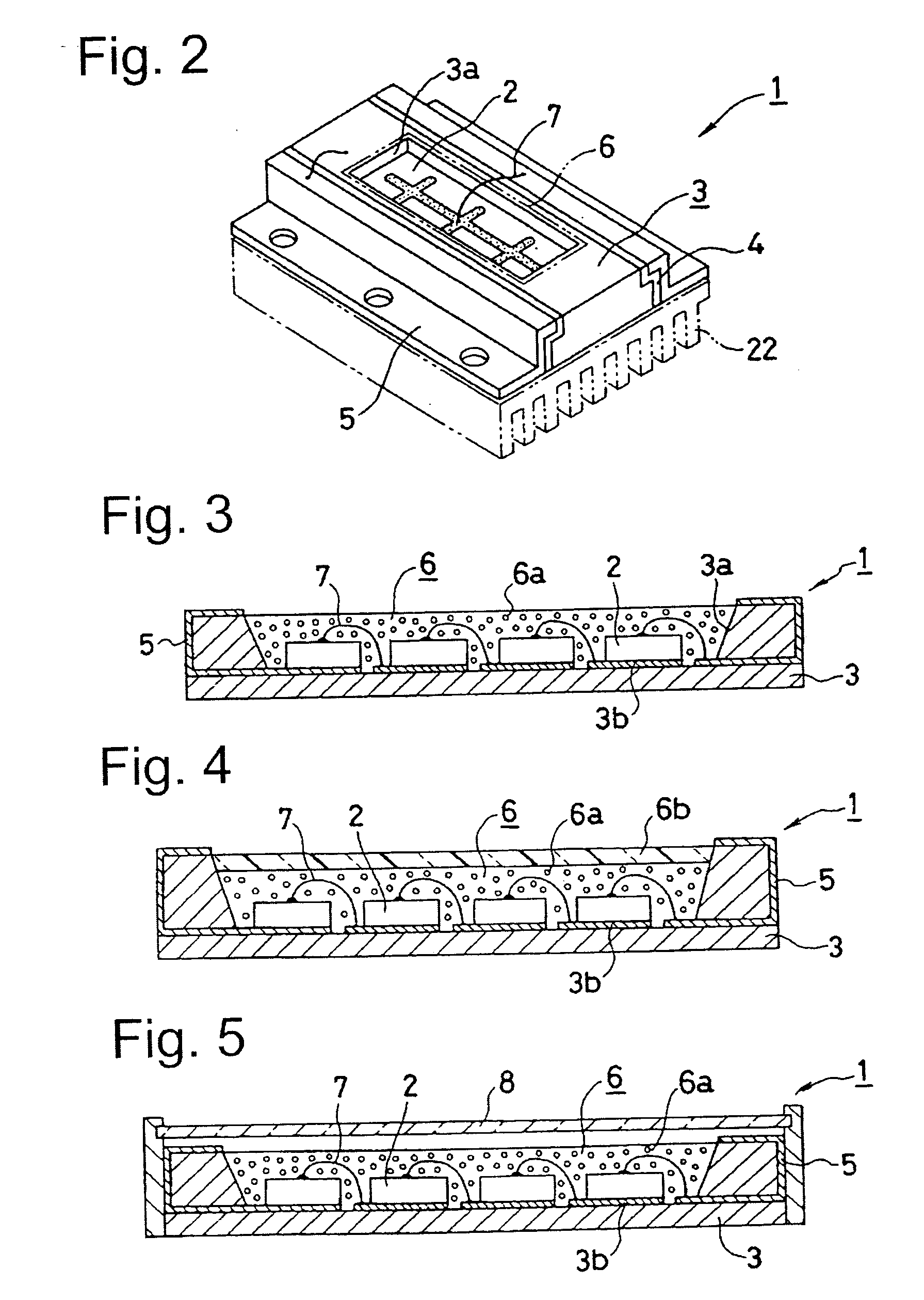
[0032] The invention will be described in detail on the basis of exemplary embodiments shown in the drawings. Referring to FIGS. 2 and 3, the reference numeral 1 denotes an LED lamp for a light source of a lighting device according to two different embodiments of the invention. In both the embodiment shown in FIG. 2 and the embodiment shown in FIG. 3, the LED lamp 1 for the light source of the lighting device includes an LED chip 2, and a base 3 on which the LED chip 2 is mounted.

[0033] In the LED lamp 1, an electric current can be applied to the LED chip 2 (as much as possible), to obtain as much amount of light as possible. Accordingly, in this case, the base 3 on which the LED chip 2 is mounted should be made of a material being superior in heat conductivity, such as a metal like copper (refer to FIG. 2), a ceramic like AIN (aluminum nitride) (refer to FIG. 3), and the like. The thickness of the base 3 should be sufficient, if desired, for thermal diffusion after connecting with...


PUM


Abstract

An LED lamp can be used as a light source of a lighting device. The LED lamp can be combined with a reflecting mirror formed as a paraboloid of revolution, to obtain desired light distribution characteristics, as with a conventional light source. The emission surface of the LED lamp for the light source of the lighting device can be rectangular, and the ratio between a short side and a long side thereof is set in a range of 1:2 to 1:6. Therefore, it is possible to form a light distribution pattern similar to that of a filament, which is conventionally used as an emission source. It is also possible to use almost all light emitted from the LED lamp as illumination light.

Description

[0001] This application claims the priority benefit under 35 U.S.C. § 119 of Japanese Patent Application No. 2004-223707 filed on Jul. 30, 2004, which is hereby incorporated by reference. BACKGROUND OF THE INVENTION [0002] 1. Field of the Invention [0003] The invention relates to an LED lamp. In particular, the invention relates to LED lamps for use in general applications, including vehicle lamps, street sign lamps, communication lamps, display lamps, etc. With regard to vehicle lamps, the invention relates to an LED lamp for a light source of a vehicle headlight which is used as an alternative to an incandescent lamp, a halogen lamp, or the like. [0004] 2. Description of the Related Art [0005]FIG. 1 shows the configuration of a conventional headlight which uses an LED lamp as a light source. In this LED headlight lamp, LEDs are arranged in a matrix of three rows and eight columns to obtain prescribed brightness. A lens and the like are provided in front of the LEDs to obtain a des...

Claims


Application Information

Patent Timeline
Patent Type & Authority Applications(United States)
IPC IPC(8): H01L33/00F21S8/10F21W101/10F21Y101/02H01L33/48H01L33/50H01L33/54H01L33/56
CPCF21K9/00H01L2924/3025F21Y2101/02H01L25/0753H01L2224/45144F21S48/115H01L2224/48465H01L2224/48091H01L2924/00014H01L2924/00F21Y2115/10F21S41/151F21S41/148
Inventor YATSUDA, YASUSHIKOIKE, TERUOOWADA, RYOTARO
Owner STANLEY ELECTRIC CO LTD
Why Eureka
Try Eureka