Multi-phase A.C. vehicle motor

Inactive Publication Date: 2006-02-02
SILICON VALLEY MICRO MCORP
View PDF12 Cites 58 Cited by
  • Summary
  • Abstract
  • Description
  • Claims
  • Application Information

AI Technical Summary

Benefits of technology

[0010] The invention has wide application to a variety of vehicles, such as an automobile, a bicycle, a motorcycle, and the like. Disk motor assemblies fabricated according to the teachings of the invention are capable of generating substantially more torque for a given size motor than conventional motors, due to the substantially greater number of magnetic components which can be mounted within a motor housing of a given size. In addition, the invention enables a multi-phase A.C. motor to be constructed having a muc

Problems solved by technology

Both design types suffer from the disadvantage that the permanent magnets of the rotor must be positioned along the circumference of the stator (either the outer circumference in the first type, or the inner circumference in the second type) in order to interact strongly with the varying magnetic field produced by the stator

Method used


Image

  • Multi-phase A.C. vehicle motor
  • Multi-phase A.C. vehicle motor
  • Multi-phase A.C. vehicle motor

Examples


Example

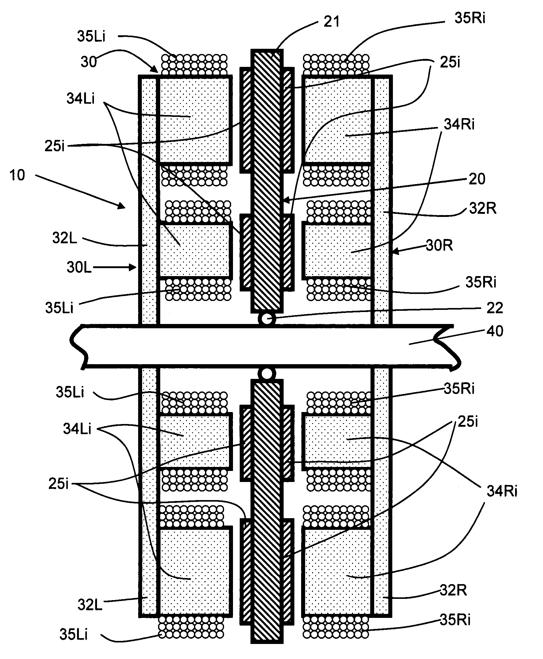
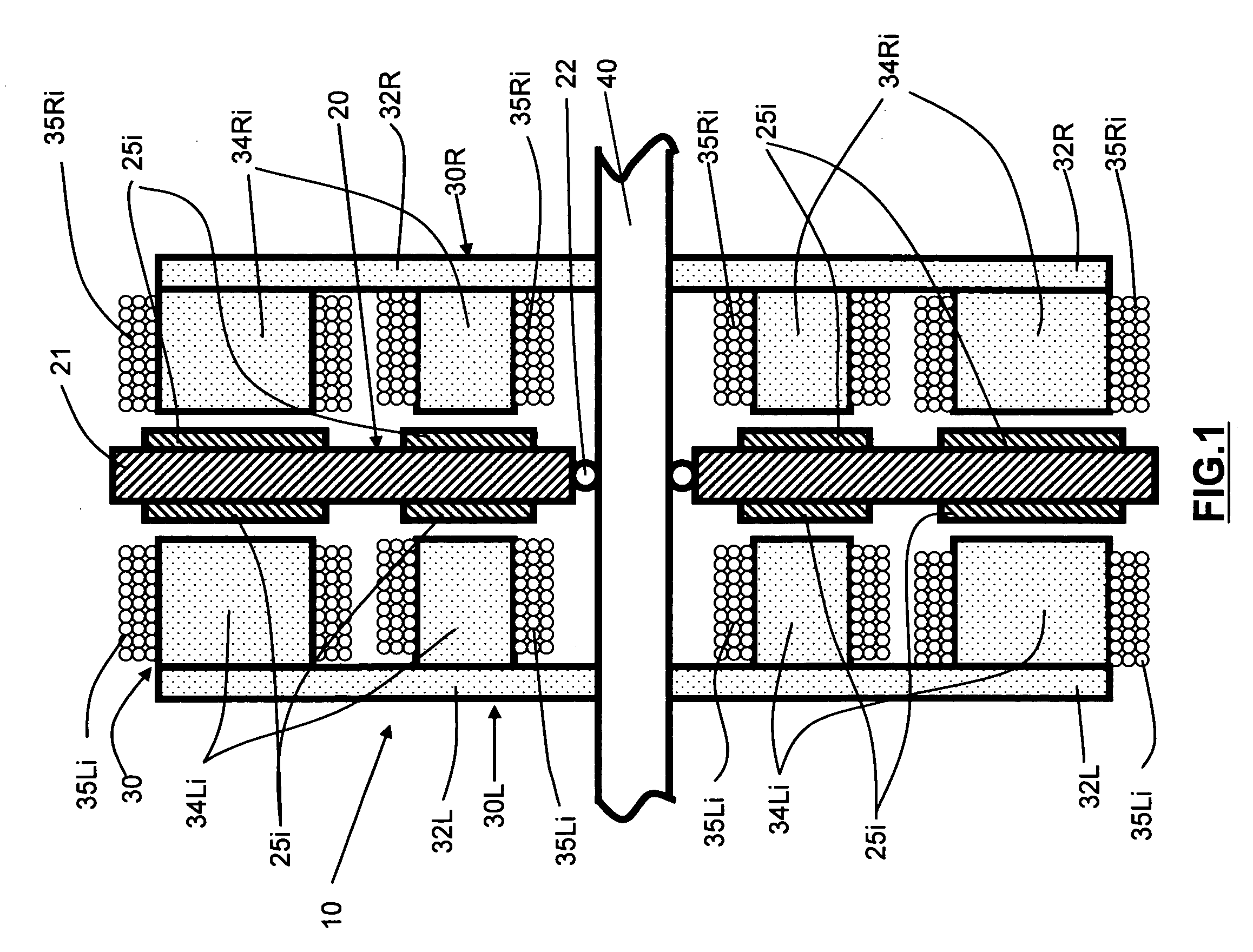
[0023] Turning now to the drawings, FIG. 1 is a sectional view of a first embodiment of the invention. As seen in this Fig., a disk motor assembly generally designated with reference numeral 10 includes a disk rotor assembly 20 and a stator assembly 30. Disk rotor assembly 20 comprises a central disk member 21 rotatably mounted by means of a standard low friction bearing 22 to a mounting shaft 40. Shaft 40 is secured to the frame of a vehicle (not shown) and serves as the mounting support for disk motor assembly 10. Shaft 40 may comprise an axle stub of an automobile, for example. Secured to opposing faces of disk member 21 are a plurality of permanent magnets 25i. Disk member 21 is fabricated from a nonmagnetic material, such as Delrin, Nylon, aluminum, or any other relatively stiff nonmagnetic material. Permanent magnets 25i are secured to the faces of disk member 21 using any one of a number of known techniques, such as adhesive bonding with a secure bonding adhesive (e.g. an epo...


PUM


Abstract

A multi-phase A.C. vehicle motor having one or more disk rotor assemblies and pairs of stator sub-assemblies. Each disk rotor assembly has a disk and a plurality of permanent magnets distributed along one or more circular paths in the disk inboard of the peripheral edge of the rotor. Each stator sub-assembly has a corresponding number of pole pieces and coils distributed along a mounting plate in corresponding circular paths. The disk is rotatably mounted to a support member; while the stator sub-assemblies are fixed to the support member.

Description

BACKGROUND OF THE INVENTION [0001] This invention relates to multi-phase A.C. motors used for the propulsion of vehicles. More particularly, this invention relates to a multi-phase A.C. vehicle propulsion motor with a compact design and improved torque. [0002] Multi-phase A.C. vehicle propulsion motors are known and have been used for the propulsion of many different types of vehicles, such as bicycles, motorcycles, autos, and small trucks. A typical motor design has a rotor and a stator. The rotor is fixedly attached to the vehicle wheel for rotation therewith and carries a plurality of permanent magnets mounted about the circumference of the rotor in a predetermined magnetic orientation. The stator is fixedly mounted to the vehicle frame and carries a plurality of electromagnets distributed in close proximity to the rotor permanent magnets. The coils of the electromagnets are coupled to a multi-phase A.C driving circuit, usually in a three-phase or Wye arrangement. Electrical powe...

Claims


Application Information

Patent Timeline
IPC IPC(8): H02K1/22H02K21/12
CPCH02K21/24H02K7/14
Inventor ZHU, SHENGBOHUANG, SU SHIONG
Owner SILICON VALLEY MICRO MCORP
Why Eureka
Try Eureka