Color balancing circuit for a display panel

a color balancing and display panel technology, applied in static indicating devices, auxillary members of forms/shuttering/falseworks, instruments, etc., can solve the problems of not providing a single convenient adjustment of overall image brightness, separate adjustment circuitry for each color, and inability to provide brightness adjustment. brightness adjustment and color balancing

Inactive Publication Date: 2006-02-02
LAPIS SEMICON CO LTD
View PDF5 Cites 111 Cited by
  • Summary
  • Abstract
  • Description
  • Claims
  • Application Information

AI Technical Summary

Benefits of technology

[0012] An object of the present invention is to provide a color balancing circuit that efficiently combines brightness adjustment with color balancing.

Problems solved by technology

Color balance can thereby be adjusted, but this system fails to provide a single convenient adjustment for overall image brightness.
This scheme provides a continuous brightness adjustment over a wide range, but does not provide for adjustment of color balance.
If a separate adjustment is made for each primary color, an arbitrary desired color balance can be obtained, but separate adjustment circuitry is required for each color and overall brightness adjustment is inconvenient, because three separate adjustments are necessary.
If a single adjustment of the driving current for all three primary colors is made, however, then although brightness adjustment is convenient and the amount of adjustment circuitry can be reduced, the color balance cannot be adjusted to suit the user's preferences, or to compensate for fabrication variations or aging changes.

Method used


Image

  • Color balancing circuit for a display panel
  • Color balancing circuit for a display panel
  • Color balancing circuit for a display panel

Examples


first embodiment

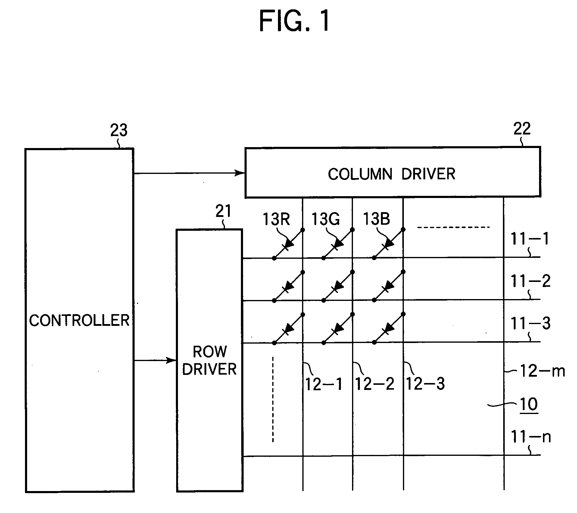
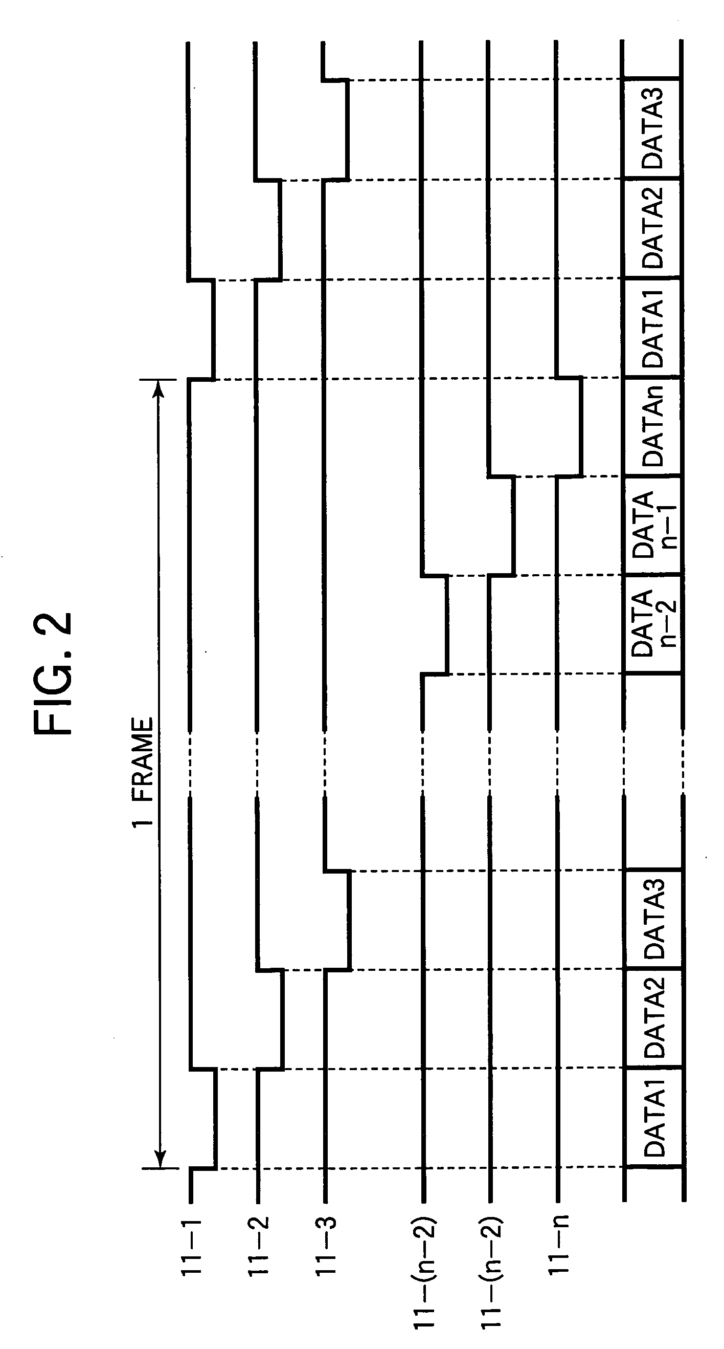
[0030] The first embodiment is employed in a display panel such as a passive matrix organic EL panel having the structure shown schematically in FIG. 1. This organic EL panel has a panel surface 10 for display of an image. A plurality of row electrodes 11-1 to 11-n extend in the row direction and a plurality of column electrodes 12-1 to 12-m extend in the column direction on the panel surface 10, where m and n are arbitrary positive integers, m being divisible by three. EL elements 13R that emit red light, EL elements 13G that emit green light, and EL elements 13B that emit blue light are disposed at the intersections of the row and column electrodes to form an n×m matrix. A triplet of EL elements 13R, 13G, and 13B constitutes a single picture element or pixel. The display surface includes a large number of these pixels.

[0031] A row driver 21 is connected to the row electrodes 11-1 to 11-n; a column driver 22 is connected to the column electrodes 12-1 to 12-m. The row driver 21 has...

second embodiment

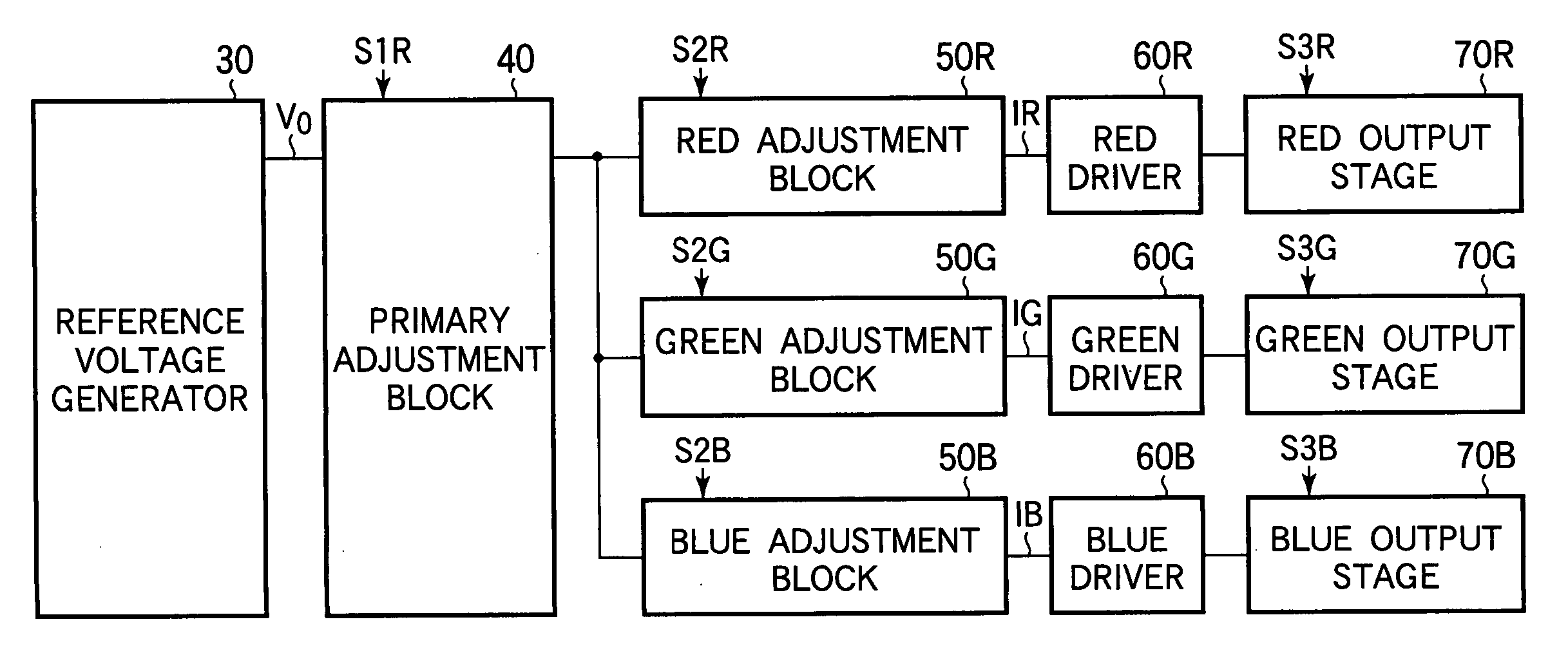
[0047] The second embodiment is a specific instance of the first embodiment, and has the general configuration shown in FIG. 3.

[0048] Referring to FIG. 4, in the second embodiment, the reference voltage generator 30 in FIG. 3 includes a power supply 31 such as a battery that supplies the reference voltage V0 to the primary adjustment block 40. The primary adjustment block 40 includes a voltage divider 41 that divides the reference voltage V0 to obtain a plurality of divided voltages, a selector 42 that selects one desired divided voltage V1 from among the divided voltages according to the brightness adjustment signal S1, and a converter circuit that generates the constant primary current I according to the selected divided voltage V1.

[0049] The voltage divider 41 has i resistors 41-1 to 41-i that divide the reference voltage V0, where i is a positive integer greater than one. The resistors 41-1 to 41-i are connected in series between the power supply 31 and ground, and output i di...

third embodiment

[0068] The third embodiment is another specific instance of the first embodiment, and has the general configuration shown in FIG. 3.

[0069] Referring to FIG. 6, the third embodiment differs from the second embodiment by replacing PMOS transistor 45 in the color balancing circuit in FIG. 4 with a PMOS transistor 145 having different characteristics, and replacing the red, green, and blue adjustment blocks 80R, 80G, and 80B with red, green, and blue adjustment blocks 180R, 180G, and 180B having different circuit configurations. PMOS transistor 145 has a channel width W=a, and a channel length L=b, where the channel size parameters (a and b) have arbitrary values.

[0070]FIG. 7 shows the circuit configuration of the red adjustment block 180R in FIG. 6. The circuit configurations of the green and blue adjustment blocks 180G and 180B are identical to the circuit configuration of the red adjustment block 180R. The red adjustment block 180R differs from the red adjustment block 80R in the s...


PUM


Abstract

A color balancing circuit for a flat panel display such as an electroluminescent display generates a primary current that can be varied to adjust the overall brightness of the display. Three currents related to the primary current by selectable ratios are generated, by current mirror circuits, for example; the ratios can be individually varied to adjust the color balance. Driving currents are generated from the three adjusted currents, by mirroring the adjusted currents, for example, and are used to drive display elements that emit light in the three primary colors. Image brightness and color balance can accordingly be adjusted separately, even though both are adjusted by adjusting the driving current. Circuit size is reduced in that the same primary current is used for all three primary colors.

Description

BACKGROUND OF THE INVENTION [0001] 1. Field of the Invention [0002] The present invention relates to a color balancing circuit for use in a flat color display panel such as an electroluminescence (EL) panel employing organic EL elements. [0003] 2. Description of the Related Art [0004] Organic EL panels are also known as organic light-emitting diode (OLED) panels. Other known types of flat panel displays include liquid crystal display (LCD) panels, non-organic light-emitting diode (LED) panels, and plasma display panels (PDPs). Two desirable qualities of these displays are an adjustable overall brightness and an adjustable balance of the brightness of the three primary colors red, green, and blue, so that colors can be accurately reproduced. [0005] Japanese Patent Application Publication No. 2001-42823 discusses the driving of an organic EL multicolor display panel having a passive matrix structure. The panel has red, green, and blue electroluminescent elements (EL elements) disposed...

Claims


Application Information

Patent Timeline
Patent Type & Authority Applications(United States)
IPC IPC(8): G09G5/10H05B44/00
CPCG09G3/3216G09G3/3283G09G2320/0666G09G2320/0606G09G2320/0626G09G2300/06E04G15/02E04G17/06E03F5/06
Inventor HARA, TETSUROKIMURA, NAOYASHIMIZU, TAKAYUKIKONDO, AKIRATAKAYANAGI, HARUYOSATOH, SHINICHI
Owner LAPIS SEMICON CO LTD
Why Eureka
Try Eureka