Disk drive with slider burnishing-on-demand

a technology of burnishing-on-demand and disk drives, applied in the direction of cleaning recording heads, maintaining head carrier alignment, magnetic recording, etc., can solve the problems of self-limiting wear, not continuing further, and initial wear-in process is fairly rapid, so as to reduce the risk of corrosion, avoid corroding, and select the time of burnishing.

Inactive Publication Date: 2006-02-02
HITACHI GLOBAS STORAGE TECH NETHERLANDS
View PDF22 Cites 16 Cited by
  • Summary
  • Abstract
  • Description
  • Claims
  • Application Information

AI Technical Summary

Benefits of technology

[0010] A disk drive is described having a capability of burnishing the sliders on demand. Each slider includes a heating element with a sufficient thermal expansion stroke to bring the area of the slider containing the transducer into contact with the disk surface to burnish the slider. Since the disk drive controls the power applied to the heater, the time of burnishing can be selected. Also, the amount of power may be selected to control the contact pressure during burnishing. Preferably the heater is used to bring the slider into contact with the disk to burnish the lowest flying part of the slider body after the drive has been assembled, and remove most or all of the overcoat and recession, and exposing the transducers at the ABS. The burnish process is performed in situ in the drive. The drive is preferably sealed hermetically to reduce the risk of corrosion after burnishing. The slider can be flown and magnetically tested prior to burnishing off the overcoat to avoid corroding the head before the drive is assembled. Using a heater to protrude the head allows burnishing without changing disk rpm or ambient pressure. Burnish times can be minimized and burnish control improved because only a very small area (the area that protrudes) comes into contact with the disk. The burnishing-on-demand of the invention can reduce magnetic spacing compared to the prior art and / or reduce the heater power and magnetic sensor temperature while the heater is on. Advantageous tradeoffs between magnetic spacing and the power / temperature budget of the heater can be made using the invention. The distribution of fly-height clearance (sigma) is reduced because a fixed power / protrusion can be used to burnish which leads to a variable amount of burnish depending on the original fly height of the heads. This variable burnishing compensates for the original variations in fly height from slider to slider by removing a variable amount of material from the slider.

Problems solved by technology

This recession contributes to the spacing between the magnetic sensor in the transducer and the magnetic material in the disk and is, therefore, undesirable.
When this level is reached, the wear will be self-limiting and not continue further because of the support provided by the ABS at the reduced disk RPM.
This initial wear-in process takes place fairly rapidly, typically within about thirty minutes.

Method used


Image

  • Disk drive with slider burnishing-on-demand
  • Disk drive with slider burnishing-on-demand
  • Disk drive with slider burnishing-on-demand

Examples


Embodiment Construction

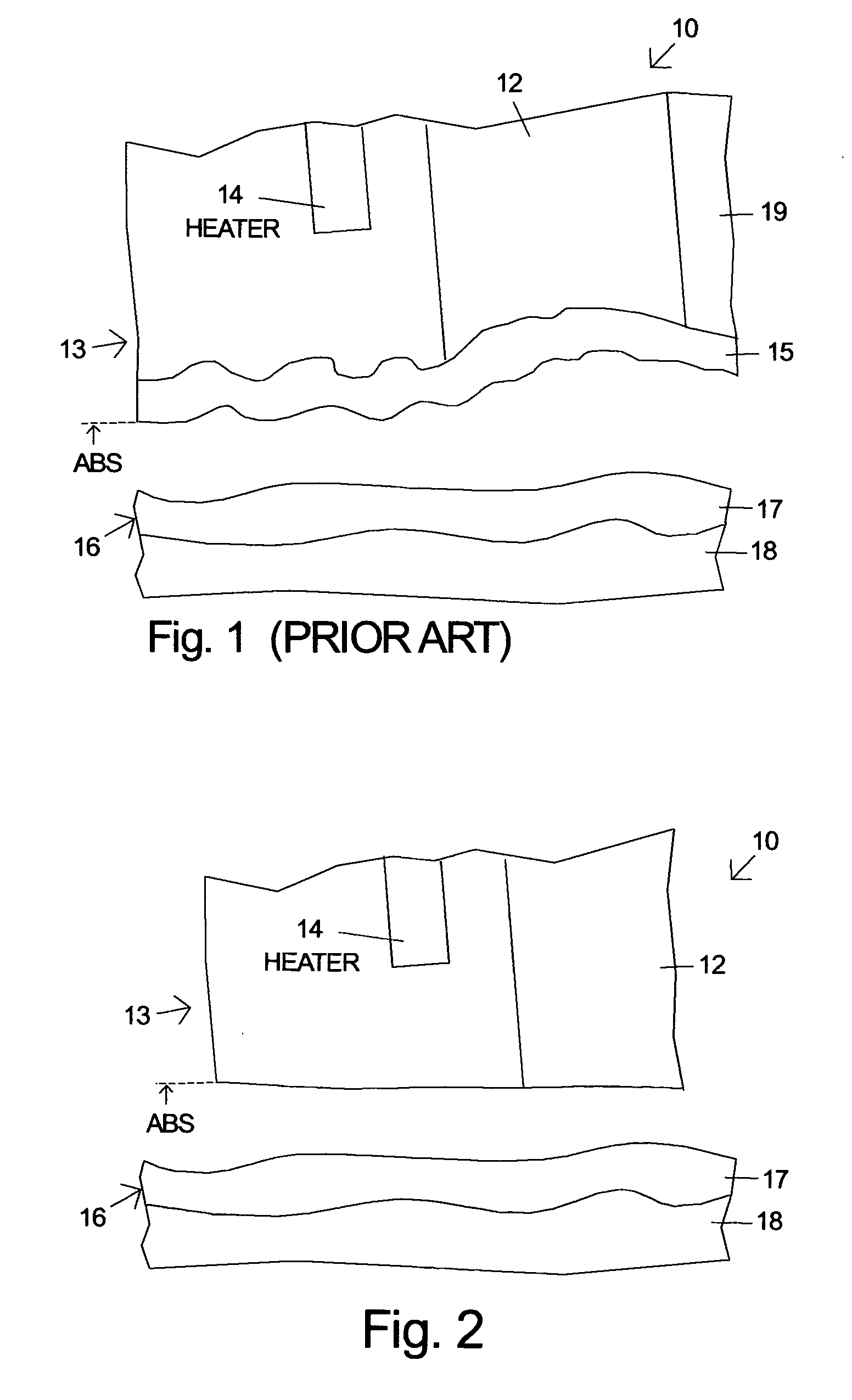
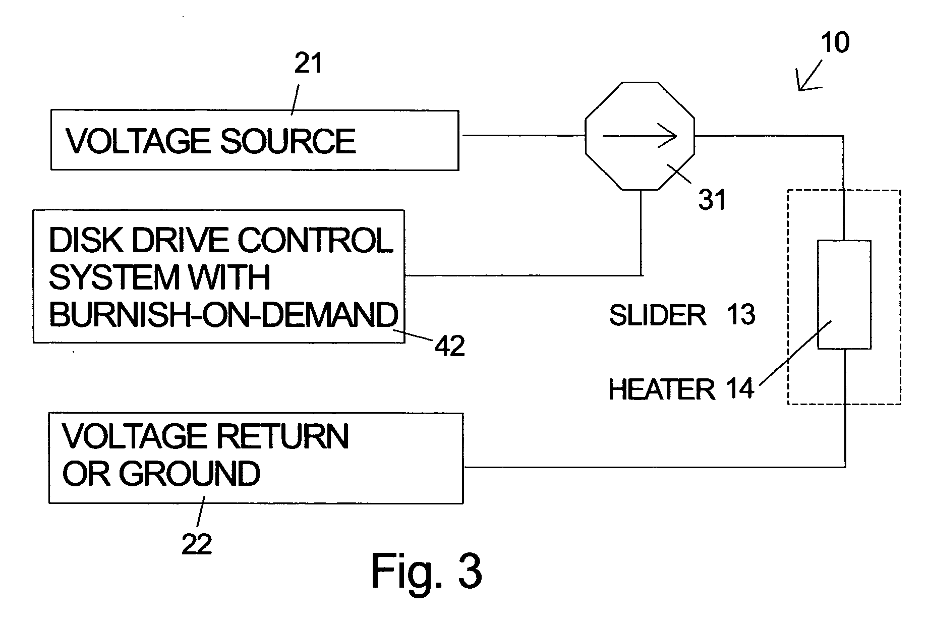
[0023] A disk drive according to the invention includes a control system which executes a burnishing operation under firmware control. A disk drive typically includes one or more sliders. A slider according to the invention includes a heat source near the read sensor which has the capacity to protrude the surface of the slider by an amount sufficient to cause contact with the disk while the disk is rotating. Unlike some other burnishing methods, the invention does not require reduced rpm and can achieve burnishing at the normal rotation speed. The heater can be a separate element 14 in the slider as shown in FIG. 2, but it is also possible to use the write coil for the heating. In the following the term heater will be used to refer interchangeably to either a separate heater or the write coil used as a heater.

[0024]FIG. 2 illustrates a disk drive 10 according to the invention after the burnishing has been performed. The slider 13 has been burnished against the disk 16 by supplying ...


PUM

PropertyMeasurementUnit
thicknessaaaaaaaaaa
thicknessaaaaaaaaaa
thicknessaaaaaaaaaa

Abstract

A disk drive is described having a capability of burnishing the sliders on demand by using a heater in the slider to thermally protrude the slider. Each slider includes a heating element with a sufficient thermal expansion stroke to bring the area of the slider containing the transducer into contact with the disk surface to burnish the slider. Preferably the heater is used to bring the slider into contact with the disk to burnish the lowest flying part of the slider body after the drive has been assembled, and remove most or all of the overcoat and recession, and exposing the transducers at the ABS. The burnish process is performed in situ in the drive and the drive is preferably hermetically sealed to reduce the risk of corrosion. The slider can be flown and magnetically tested prior to burnishing off the overcoat to avoid corroding the head before the drive is assembled.

Description

RELATED APPLICATION [0001] A co-pending, commonly assigned application bearing Ser. No. 10 / 673,593 describing a hermetically sealed HDD enclosure which can be used in one of the embodiments of the present invention was filed on Sep. 29, 2003. This application is hereby incorporated herein by reference.FIELD OF THE INVENTION [0002] The invention relates to sliders used in disk drives and more particularly to methods and means for burnishing the slider in situ in a disk drive. BACKGROUND OF THE INVENTION [0003] Selected components of a prior art magnetic disk drive 10 are illustrated in FIG. 1. A slider 13 containing magnetic transducers 12 for reading and writing magnetic transitions is urged toward the rotating disk 16 by a suspension (not shown). As the disk rotates an air-bearing develops under the slider and causes it to fly. The slider has an overcoat 15 which provides corrosion protection for the metals in the magnetic transducers 12. The disk 16 typically includes a thin film ...

Claims


Application Information

Patent Timeline
Patent Type & Authority Applications(United States)
IPC IPC(8): G11B5/10G11B5/127G11B5/41G11B5/60G11B15/64G11B17/32G11B21/20
CPCG11B5/3133G11B5/6064G11B5/6005G11B5/3136
Inventor STIPE, BARRY CUSHING
Owner HITACHI GLOBAS STORAGE TECH NETHERLANDS
Why Eureka
Try Eureka