Flat optical fiber light emitters

a technology of optical fibers and light emitters, which is applied in the field of flat optical fiber light emitters, can solve the problems of difficult control of the thickness of injection molded light emitting panels, films, sheets and plates, and the relatively high cost of manufacture of light emitting members out of optical fibers, and achieves the effects of increasing efficiency, reducing manufacturing costs, and reducing manufacturing costs

Inactive Publication Date: 2006-02-02
LUMITEX
View PDF22 Cites 119 Cited by
  • Summary
  • Abstract
  • Description
  • Claims
  • Application Information

AI Technical Summary

Benefits of technology

[0007] The light emitting members of the present invention are made out of optical fibers instead of light emitting panels, films, sheets or plates for increased efficiency in keeping the light in longer and allowing the light to be distributed / emitted where desired. However, instead of using round optical fibers, flat optical fibers are used which have the advantage that more surface area of the flat optical fibers can be disrupted using known marring or abrading techniques for increased brightness for a given light emitting surface area.
[0008] Another advantage in making light emitting members out of flat optical fibers instead of round optical fibers is that the ends of the flat optical fibers need not be bundled and secured together by a connector assembly to serve as an interface between the fiber ends and the light source as do round optical fibers. Flat optical fibers may be manufactured in different thicknesses and widths to make it easier and more efficient to couple one or more light sources including particularly surface mount light sources such as surface mount light emitting diodes to the flat optical fiber ends. Surface mount light emitting diodes are generally rectangular in cross section, which makes it relatively easy to optically couple them to the ends of flat optical fibers by making the flat optical fibers of substantially the same thickness and either the same or greater width than the light sources. If the flat optical fibers have a width substantially greater than that of the light sources, multiple light sources may be optically coupled to the end of each optical fiber to provide for increased brightness. Also because the ends of the flat optical fibers need not be bundled together by a connector assembly to serve as an interface between the optical fiber ends and the light sources, the need for space to receive and store bundled round optical fiber ends is eliminated.
[0009] Still another advantage in making light emitting members out of flat optical fibers instead of round optical fibers is that a fewer number of wider flat optical fibers may be used to produce an equivalent light output. Flat optical fiber light emitters may be comprised of one or more flat optical fibers depending on the light output requirements of the light emitters. Where multiple flat optical fibers are used, the flat optical fibers may be held together or mounted separately and may if desired have gaps therebetween for lighting different areas of a display including for example a liquid crystal display, a graphic overlay or different rows of keys of a keyboard or the like.
[0015] In accordance with another aspect of the invention, the thickness of the flat optical fibers may substantially correspond to the thickness of the light sources including particularly surface mount light sources such as surface mount light emitting diodes (including polymer light emitting diodes and organic light emitting diodes) for ease of optically coupling the light sources to the flat optical fibers.
[0016] In accordance with another aspect of the invention, the flat optical fibers may be of different widths which may be the same or greater than the width of the light sources. If the width of the flat optical fibers is substantially greater than that of the light sources, multiple light sources may be optically coupled to each flat optical fiber for increased brightness.

Problems solved by technology

However, such light emitting panels, films, sheets and plates are not as efficient in transmitting light as light emitting members made out of optical fibers because they lack the cladding that optical fibers have to keep the light in longer and allow the light to be distributed / emitted where desired.
Also it is difficult to control the thickness of injection molded light emitting panels, films, sheets and plates because of the stresses that occur in different areas of the light emitting members during cooling after molding.
Heretofore a major drawback in making light emitting members out of optical fibers was the relatively high cost of manufacture.
Also because the optical fibers used were round optical fibers of relatively small diameter, only a relatively small surface area of each optical fiber could be disrupted during the manufacturing process as compared to the amount of surface area of light emitting panels, films, sheets and plates that could be disrupted.
This limited the relative overall brightness of light emitting members made of optical fibers as compared to light emitting panels, films, sheets and plates for a given light emitting surface area.
Another disadvantage of previous light emitting members made of optical fibers was that the ends of the optical fibers had to be bundled and secured together by a connector assembly that served as an interface between the optical fiber ends and a light source.
Also it was difficult efficiently to couple a light source to such bundled optical fiber end portions because of the minute gaps between the optical fiber end portions and the irregular shape of the bundled optical fiber end portions.

Method used


Image

  • Flat optical fiber light emitters
  • Flat optical fiber light emitters
  • Flat optical fiber light emitters

Examples


Embodiment Construction

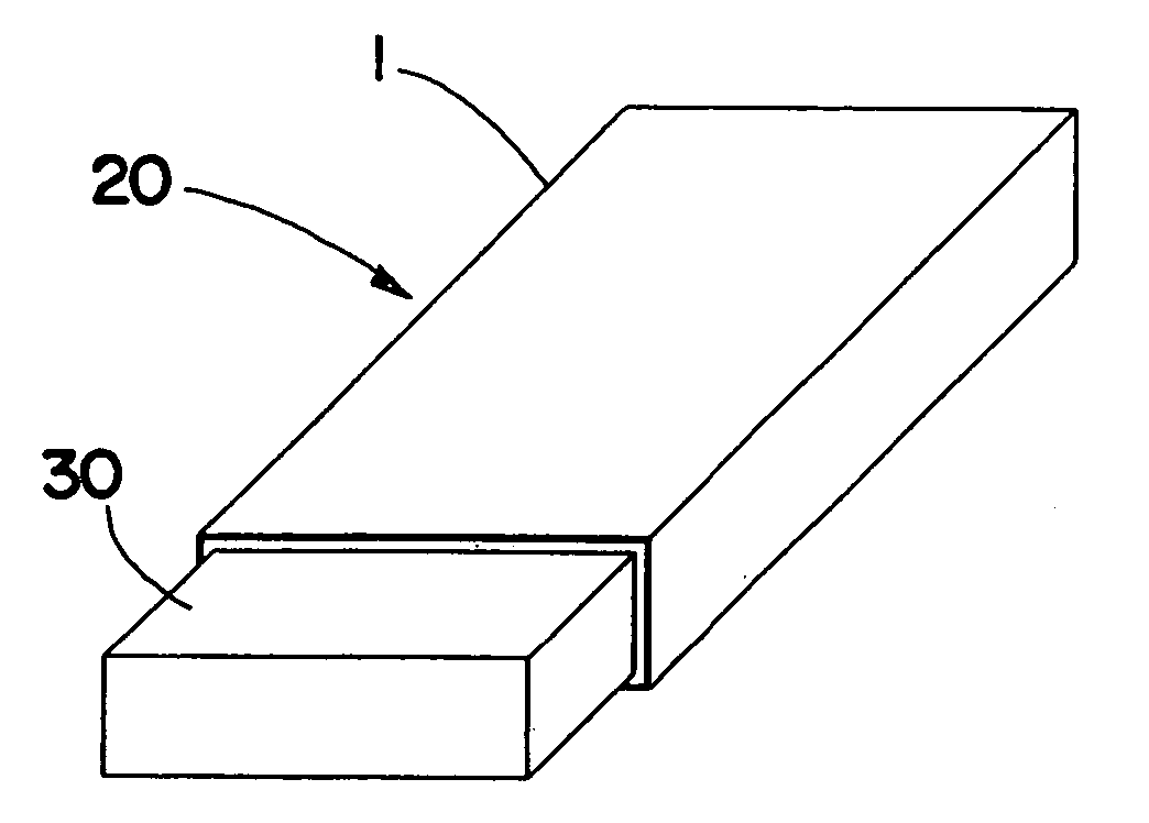
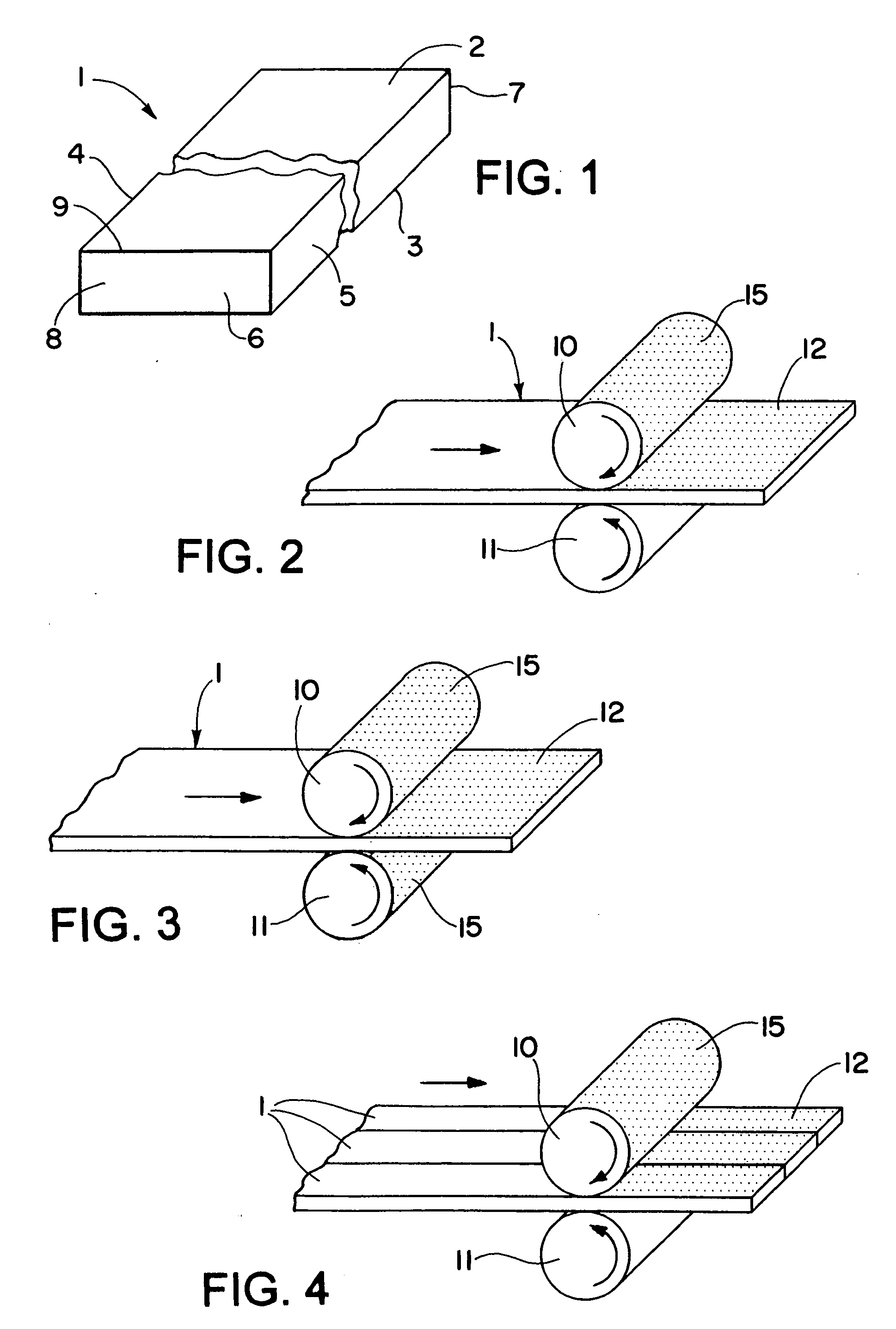
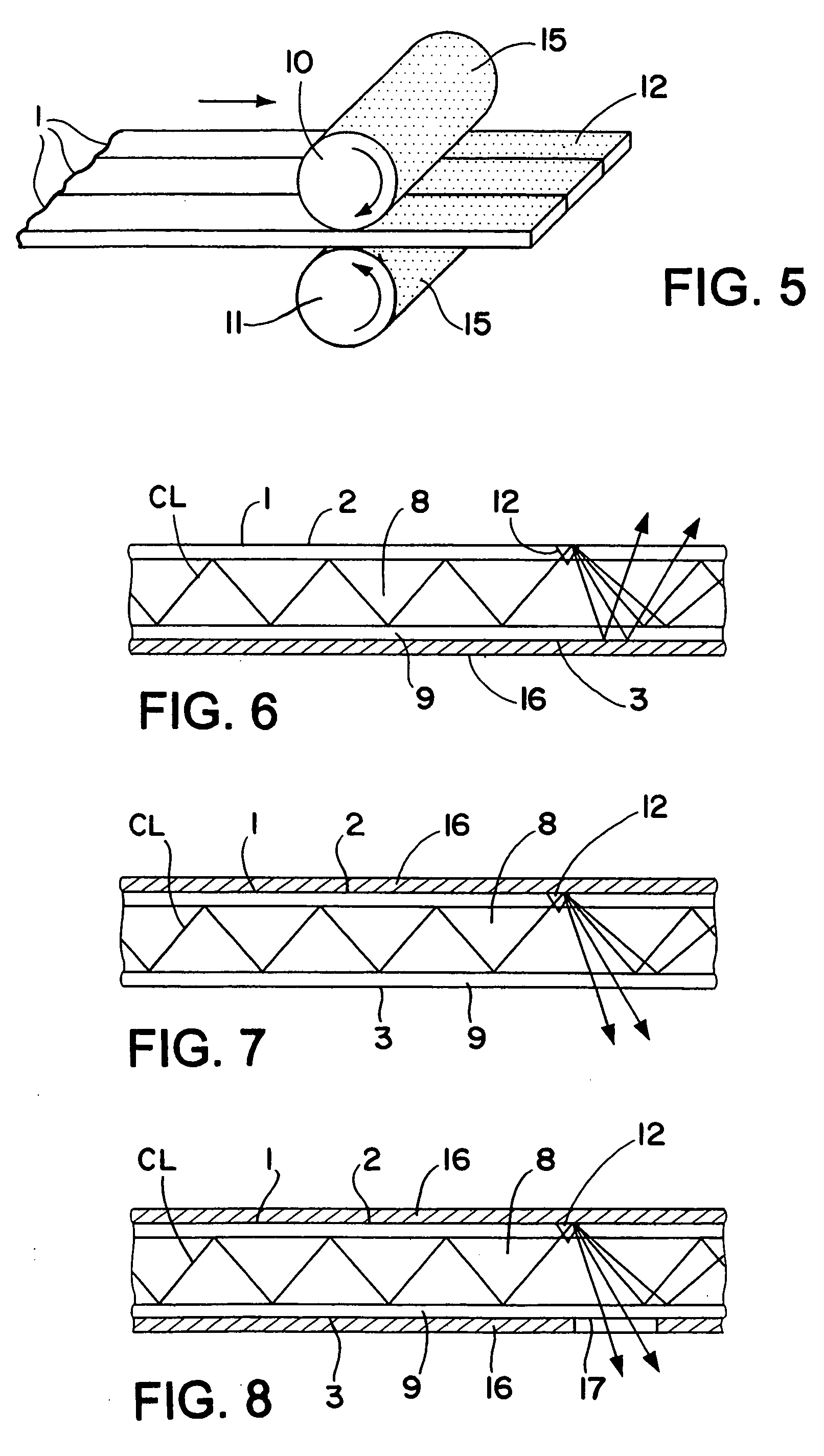
[0042] Referring now in detail to the drawings, wherein the same reference numbers are used to designate like parts, and initially to FIG. 1, there is shown a flat optical fiber 1 of any desired length having opposite flat sides 2 and 3 and opposite side edges 4 and 5 and ends 6 and 7. The flat optical fiber 1 has a light transmitting core portion 8 made of a suitable optically transparent material such as glass or plastic having the desired optical characteristics and flexibility. Surrounding the core portion 8 is an outer sheath or cladding 9 having an index of refraction that is different than that of the core material, whereby substantially total internal reflection is obtained at the core-cladding interface, as well known in the art.

[0043] To cause conducted light entering one or both ends of one or more flat optical fibers 1 to be emitted from one or both sides 2 and 3 thereof, the flat optical fibers may be disrupted at one or more areas along their length as by roughening, ...


PUM

PropertyMeasurementUnit
thicknessaaaaaaaaaa
widthaaaaaaaaaa
widthaaaaaaaaaa

Abstract

Light emitters are made of one or more cladded flat optical fibers having opposite flat sides and disruptions along at least a portion of the length of the fibers to cause light entering at least one end to be emitted from at least one side. The ends of the flat optical fibers may have substantially the same thickness as a light source and a width substantially equal to or substantially greater than the width of the light source for ease of optically coupling one or more such light sources to the flat optical fiber ends.

Description

FIELD OF THE INVENTION [0001] This invention generally relates to light emitting members made of flat optical fibers that emit light received through one or both ends out one or both sides to provide a desired light output distribution. BACKGROUND OF THE INVENTION [0002] It is generally known to make light emitting members out of light conducting panels, films, sheets, plates and optical fibers. Light entering one or both ends of the light emitting members may be emitted from one or both sides by providing disruptions on one or both sides in a desired pattern. [0003] An advantage in making light emitting members out of panels, films, sheets and plates is that they are relatively inexpensive to make. However, such light emitting panels, films, sheets and plates are not as efficient in transmitting light as light emitting members made out of optical fibers because they lack the cladding that optical fibers have to keep the light in longer and allow the light to be distributed / emitted ...

Claims


Application Information

Patent Timeline
Patent Type & Authority Applications(United States)
IPC IPC(8): G02B6/10G02B6/02
CPCG02B6/002G02B6/10G02B6/0073G02B6/0036D03D15/00F21V7/04G02B6/0011G02B6/02G02B6/44G09F13/18G02B6/004G02B6/0021
Inventor PAGE, DAVID J.SPAHNIE, BRIAN M.
Owner LUMITEX
Why Eureka
Try Eureka