
Image forming apparatus

Inactive Publication Date: 2006-02-02
CANON KK
View PDF28 Cites 40 Cited by
  • Summary
  • Abstract
  • Description
  • Claims
  • Application Information

AI Technical Summary

Benefits of technology

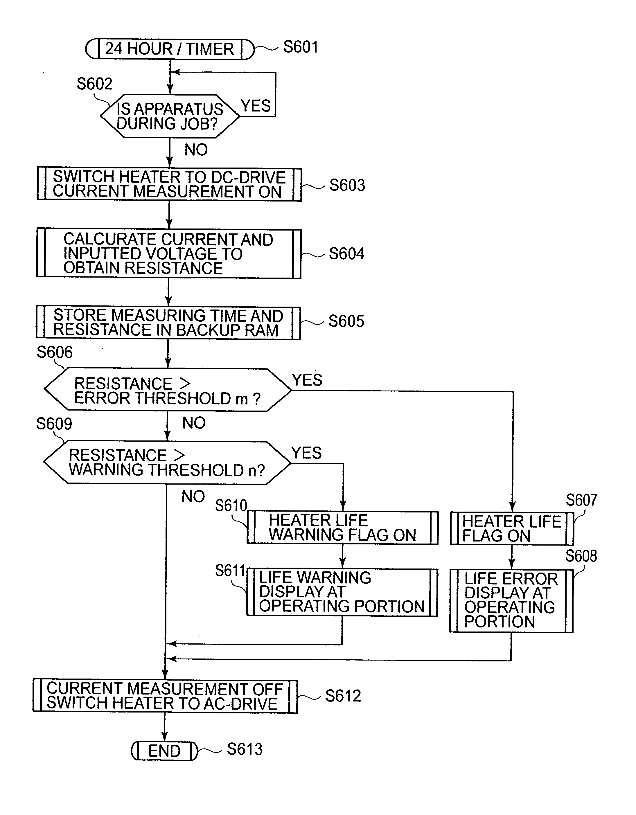
[0007] An object of the present invention is to provide an image forming apparatus capable of performing detection and estimate of end of life of a heater with good accuracy.
[0013] By the image forming apparatus according to the present invention, it is possible to detect the end of life of the heating means with good accuracy. Accordingly, it is possible to reduce a running cost of the apparatus. Further, downtime of the image forming apparatus due to replacement of the heating means can be reduced as smaller as possible.

Problems solved by technology

However, according to the conventional methods, there have arisen such problems that the end of life is detected although the heater does not actually reach its end of life and thus replacement of the heater is required, that it is on the basis of an actual temperature of the fixation roller but the temperature is not accurately measured due to an ambient temperature environment, another heating means, and the kind and size of sheet used, and that the end of life is suddenly detected depending on a temperature rise state of the fixation roller.
For this reason, particularly in the case where a heater has a longer life than a main assembly, when the heater is reused, there has arisen a problem that a detection accuracy of the life is remarkably impaired.

Method used


Image

  • Image forming apparatus
  • Image forming apparatus
  • Image forming apparatus

Examples


Embodiment Construction

[0024] Hereinbelow, embodiments of the present invention will be exemplarily described more specifically. In the following description, it should be understood that dimensions, materials, shapes, relative arrangement, and the like of constitutional parts in the present invention are not intended to be limited to those described specifically unless otherwise specified. Further, unless otherwise specified again, the materials, the shapes, and the like of members once described are the same as those in the previous description.

(Schematic Constitution of Image Forming Apparatus)

[0025] First, a schematic constitution of a copying machine of an electrophotographic-type as an example of an image forming apparatus to which the present invention is suitably applicable will be described.

[0026]FIG. 3 is a schematic sectional view of the image forming apparatus according to this embodiment.

[0027] A copying machine (hereinafter referred to as an “image forming apparatus”) A includes an orig...


PUM


Abstract

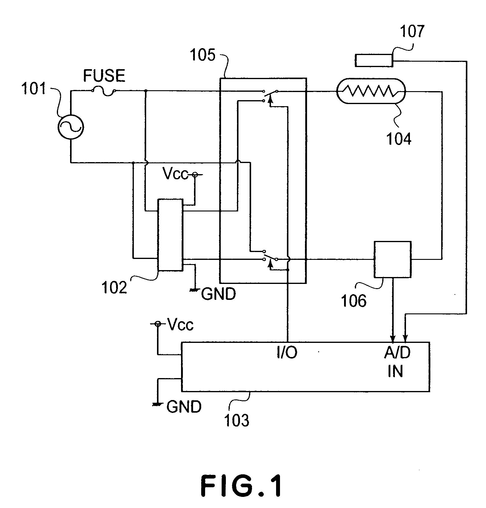
An image forming apparatus includes fixing means for fixing a toner image formed on a recording material, and heating means, for heating the fixing means, comprising a carbon-based material. In order to detect and expect the life of the heating means with good accuracy, the image forming apparatus further comprises current measuring means for measuring a current passing through the heating means and notification means for providing notification of information on a life of the heating means depending on an output of the current measuring means.

Description

FIELD OF THE INVENTION AND RELATED ART [0001] The present invention relates to an image forming apparatus using electrophotography or electrostatic recording, particularly an image forming apparatus, such as a copying machine, a printer, FAX (facsimile) machine, or the like. [0002] An image forming apparatus, for performing heat fixation of an image with respect to a sheet, such as a copying machine or printer of an electrophotographic type is constituted by respective units of developing apparatus, a latent image apparatus, a transfer apparatus, a fixing apparatus, and the like. Respective parts of these units have a different life (span) for each part. For this reason, in order to provide a user with always stable image output, it is necessary to appropriately setting the life so as to effect indication of life warning or estimation of remaining time to the user and display which urges the user to replace the part. [0003] Of the above described units of the image forming apparatus...

Claims


Application Information

Patent Timeline
IPC IPC(8): G03G15/20
CPCG03G15/2064G03G15/553G03G2221/1663
Inventor KUROKI, KENJIKOGA, KATSUHIDENAKAZATO, JUNOHTA, TOMOICHIROYAMAZAKI, YOSHITAKASEKIGUCHI, NOBUO
Owner CANON KK
Learn More