Gas supply blowout nozzle and method of producing flame-proofed fiber and carbon fiber

a technology of blowout nozzle and gas supply, which is applied in the direction of dryers, lighting and heating apparatus, furnaces, etc., can solve the problems of unsatisfactory product quality, smoke or breakage of fibers, etc., and achieve the effect of reducing the running cost reducing the power load of the blowing fan, and suppressing resistan

Active Publication Date: 2016-06-09
MITSUBISHI CHEM CORP
View PDF11 Cites 2 Cited by
  • Summary
  • Abstract
  • Description
  • Claims
  • Application Information

AI Technical Summary

Benefits of technology

[0025]Since the gas supply blowout nozzle of the heat treatment furnace of the invention employs the above-described configuration, it is possible to suppress resistance generated when a necessary volume of a gas is blown into the heat treatment furnace and hence to decrease the power load of the blowing fan.
[0026]Further, when the flame-proofed fiber and the carbon fiber are produced according to the above-described production method, it is possible to decrease the running cost of the blowing fan necessary for the heat treatment furnace and hence it is possible to provide the low-cost carbon fiber.
[0027]Further, since the porous plate is not used inside the gas passage in the gas supply blowout nozzle of the present invention, blockage of the porous plate of the blowout nozzle by suspended solid materials in the atmosphere does not occur. For that reason, it is possible to solve the non-uniformity in the quality of the product caused by degradation in wind speed distribution of the gas supplied into the heat treatment furnace caused by the blockage of the porous plate in production. Further, since there is no need to clean the porous plate, the burden of a worker decreases and the production can be continuously performed for a long period of times. Accordingly, it is possible to realize a stable production and to improve production efficiency.

Problems solved by technology

Here, when the wind speed or the temperature in the hot air is not uniform, the flame-proofing reaction would not be uniform, and hence troubles such as smoke or breakage of fibers occurs.
Further, the quality of the product is not uniform.

Method used


Image

  • Gas supply blowout nozzle and method of producing flame-proofed fiber and carbon fiber
  • Gas supply blowout nozzle and method of producing flame-proofed fiber and carbon fiber
  • Gas supply blowout nozzle and method of producing flame-proofed fiber and carbon fiber

Examples


example 1

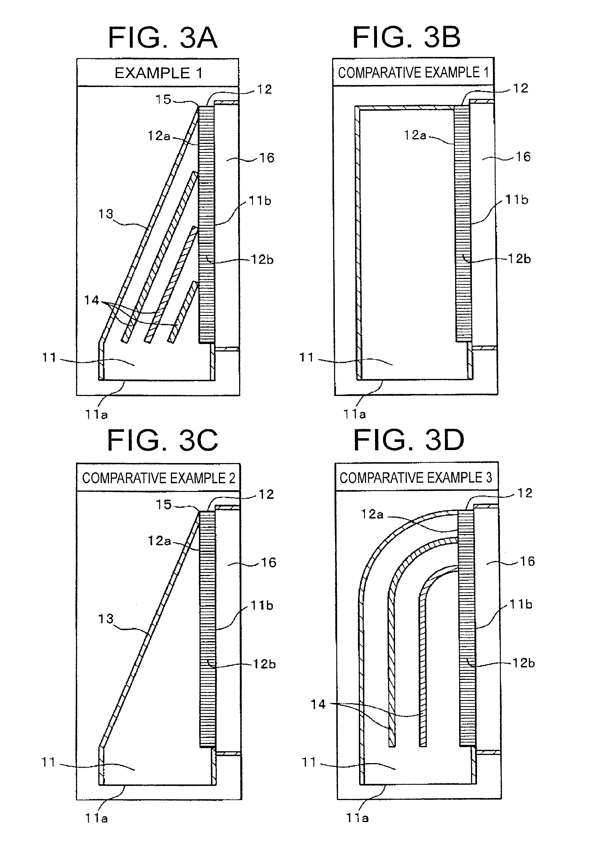
[0059]FIG. 3(a) illustrates the gas supply blowout nozzle 11 according to Example 1 of the present invention. Then, the specific dimension or the measurement result is shown in Table 1.

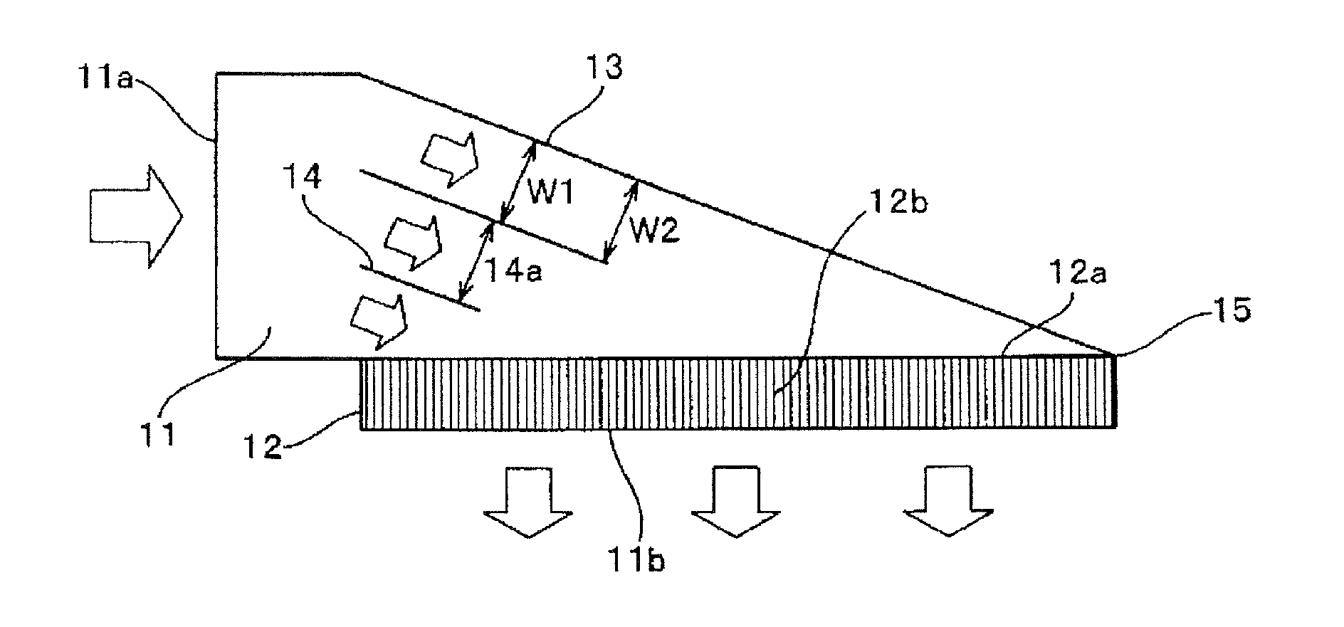
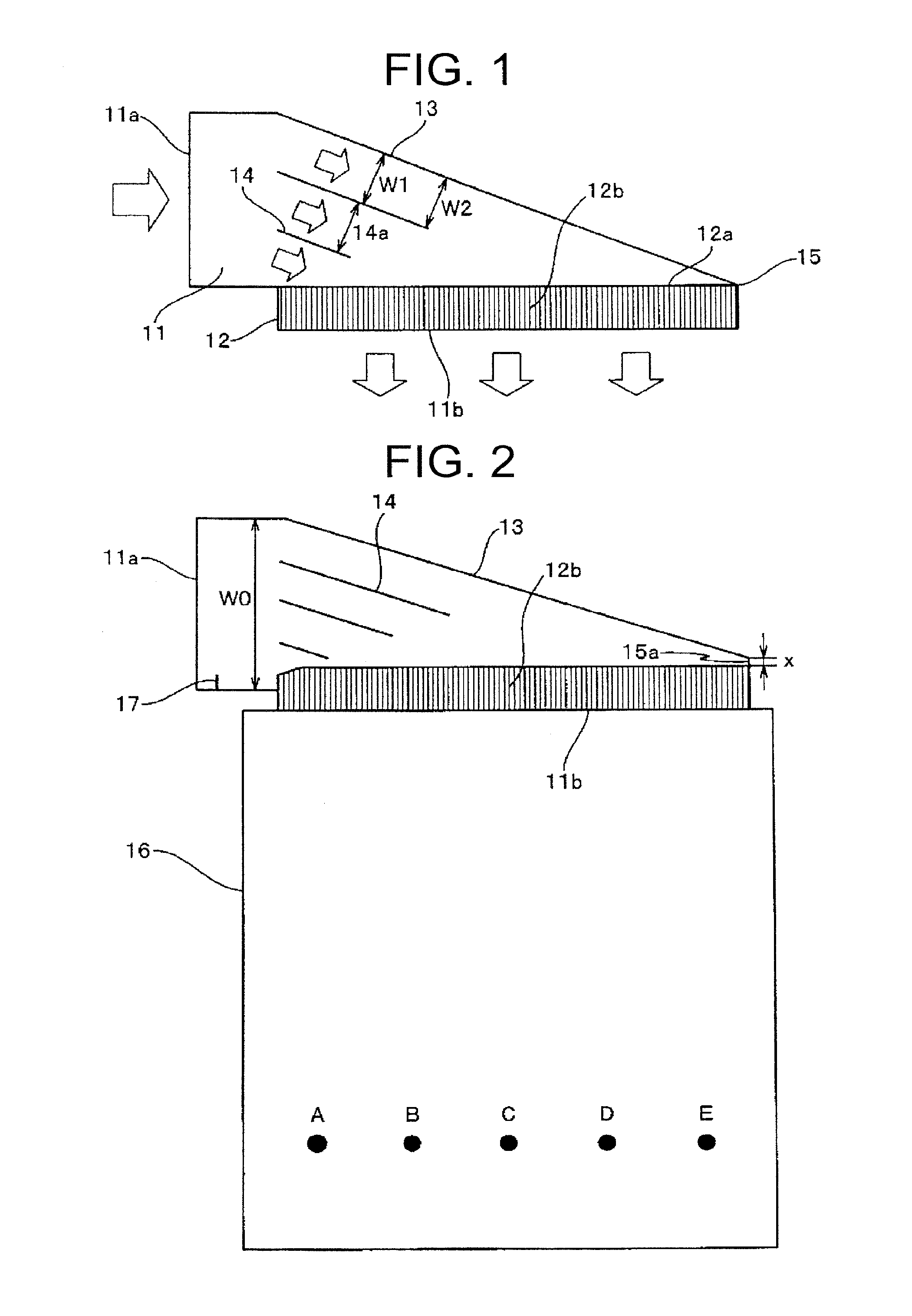
[0060]Three guide plates 14 and the straightening plate 12b having a uniform length were provided inside the tapered nozzle of which the width and the height of the gas inlet port 11a were respectively 750 mm and 155 mm and the width of the gas outlet port 11b was 2,000 mm. The guide plates 14 were provided on a line connecting a point dividing a distance from the start end position of the inclined plate 13 to the opposite wall in the passage width direction to a point dividing the gas inlet 12a of the rectification board in the same manner, and the passage width W1 perpendicular to the gas passages formed between the guide plates 14 and the gas passage formed by the inclined plate 13 and the guide plate 14 was uniform. As the rectification board 12, a plurality of plates having a length of 80 mm and ...

example 2

[0068]FIG. 4(a) illustrates the gas supply blowout nozzle 11 according to Example 2 of the present invention.

[0069]Three guide plates 14 and the straightening plate 12b having a uniform length were provided inside the tapered nozzle body of which the width and the height of the gas inlet port 11a were respectively 750 mm and 155 mm and the width of the gas outlet port 11b was 2,000 mm. The position of the guide plate 14 was the same as Example 1. The straightening plates 12b originally having a length of 80 mm and a plate thickness of 1 mm were provided every 20 mm inside the gas outlet port 11b having a width of 2,000 mm. A portion of the rectification board—from the gas inlet port side end in the length of 100 mm was tapered so that the gas inlet 12a of the outermost end contacts the side surface of the nozzle body. Here, the ratio L / P between the length L of the length direction and the pitch P of the straightening plate was 4.0, and the total area ratio t / P of the straightening ...

example 3

[0070]FIG. 4(b) illustrates the gas supply blowout nozzle 11 according to Example 3 of the present invention.

[0071]Three guide plates 14 dividing the passage into four parts, the flat plate-shaped stream separation plate 17 having a length of 40 mm, and the straightening plates 12b were provided inside the tapered nozzle of which the width and the height of the gas inlet port 11a were respectively 750 mm and 155 mm and the width of the gas outlet port 11b was 2,000 mm. Here, the area Sh of the stream separation plate 17 projected to the cross-section in the perpendicular direction of the stream separation plate 17 was 1 / 19 of the opening area Si of the gas inlet port 11a. The straightening plates 12b each having a length of 80 mm and a plate thickness of 1 mm were provided every 20 mm inside the gas outlet port 11b having a width of 2,000 mm. A taper is formed by changing the length of the straightening plate in the width of 100 mm near the gas inlet port. At this time, the ratio L / ...


PUM

PropertyMeasurementUnit
distanceaaaaaaaaaa
temperatureaaaaaaaaaa

Abstract

The nozzle body of the gas supply blowout nozzle (11) includes an inclined plate (13) guiding a gas flowing straightly from a gas inlet port to a rectification board (12), which is connected with the nozzle body. The rectification board (12) rectifies the flow of the gas guided by the inclined plate (13) so that the gas blows out perpendicular or parallel to a yarn from a gas outlet port. A gas guiding zone formed between the inclined plate (13) and the rectification board (12) includes one or more guide plates (14) which divide the gas supplied from the gas inlet port (11a) of the gas supply blowout nozzle (11) into two or more streams. In each gas passage formed at least one of between the inclined plate (13) and the guide plate (14) or between the guide plates (14), an upstream passage width W1 and any downstream passage width W2 thereof satisfy the relation of W1≧W2. The opening area A of the gas inlet port (12a) and the opening area B of the gas inlet of the rectification board (12) may satisfy the relation of A≦B. By means of said configuration, the wind speed in the heat treatment furnace is made uniform, the non-uniformity in the quality of the product caused by the non-uniformity of the wind speed is eliminated, longtime stable production is enabled, production efficiency is increased, and running costs are decreased.

Description

TECHNICAL FIELD[0001]The present invention relates to a gas supply blowout nozzle capable of changing a gas blowing direction and a method of producing a flame-proofed fiber and a carbon fiber using the gas supply blowout nozzle.BACKGROUND ART[0002]Generally, a polyacrylonitrile based carbon fiber is obtained by a flame-proofing treatment at 200° C. or more in an oxidizing atmosphere and a carbonizing treatment at 300° C. or more in an inert atmosphere. In a flame-proofing step, a flame-proofing reaction is started when the temperature of a precursor fiber bundle is increased by hot air. Further, the flame-proofing reaction is controlled by removing the reaction heat of the flame-proofing reaction. Here, when the wind speed or the temperature in the hot air is not uniform, the flame-proofing reaction would not be uniform, and hence troubles such as smoke or breakage of fibers occurs. Further, the quality of the product is not uniform. Therefore, there is a need to remove unevenness ...

Claims


Application Information

Patent Timeline
Patent Type & Authority Applications(United States)
IPC IPC(8): D01F9/32D01D10/02F26B21/00D01F9/22
CPCD01F9/32D01F9/22D10B2101/12F26B21/004D01D10/02B05B1/14F27B9/28D02J13/00B05B1/3402B05B1/34
Inventor ARAI, RISAKAJI, SATOSHIKAWAMURA, ATSUSHI
Owner MITSUBISHI CHEM CORP
Why Eureka
Try Eureka