Sealing device and rolling bearing apparatus

a technology of sealing device and rolling bearing, which is applied in the direction of sealing, mechanical equipment, transportation and packaging, etc., can solve the problems of raceway surface, failure of lubrication of rolling element, and significant problem, so as to reduce the running cost of the machine having the bimetal member

Inactive Publication Date: 2009-09-17
JTEKT CORP
View PDF4 Cites 2 Cited by
  • Summary
  • Abstract
  • Description
  • Claims
  • Application Information

AI Technical Summary

Benefits of technology

[0033]According to the embodiment, when a machine having the sealing device is operated, by utilizing a temperature rise of the bimetal member, a function of increasing the interval between the first member and the second member can be promoted.
[0034]Further, according to the embodiment, when the temperature of the bimetal member is equal to or larger than the predetermined temperature, the current supplied to at least one of the first portion and the second portion can be reduced, and therefore, a running cost of the machine having the bimetal member can be reduced.

Problems solved by technology

The inventors have found that there poses the following problem in a rolling bearing apparatus having a large variation in a temperature between that when the apparatus is used and that when the apparatus is stopped as in a rolling bearing apparatus for a machine tool or the like.
Therefrom, a failure in lubrication is brought about by reducing a hardness of a lubricant at inside of the bearing or the like by the foreign matter invading from outside.
The problem becomes significant when the foreign matter invading inside when the apparatus is stopped is a water base mist (for example, when a working oil or the like is included).
That is, in such a case, the water base mist is brought to between a rolling element and a raceway surface, and a failure in lubrication of the rolling element and the raceway surface is brought about.

Method used


Image

  • Sealing device and rolling bearing apparatus
  • Sealing device and rolling bearing apparatus
  • Sealing device and rolling bearing apparatus

Examples


first embodiment

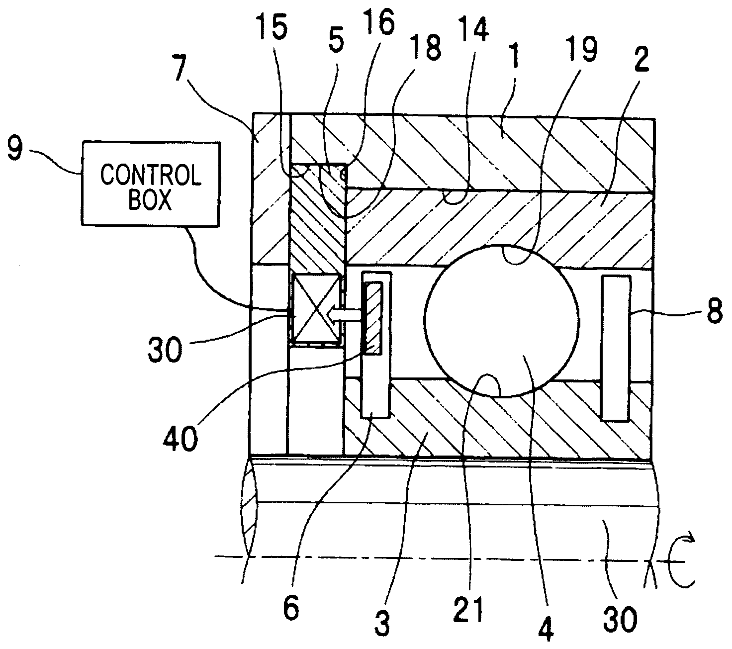
[0051]FIG. 1 is a schematic sectional view in an axial direction of a ball bearing apparatus according to the invention.

[0052]The ball bearing apparatus includes an axle box 1, an outer ring 2, an inner ring 3 as a second raceway member, a plurality of balls 4 constituting a plurality of rolling elements, a sealing device, a ring-like member 7, and a seal member 8, and the sealing device includes a first portion 5, a second portion 6, and a control box 9 as a control portion.

[0053]An inner peripheral face of the axle box 1 includes a first circular cylinder inner peripheral face 14, and a second circular cylinder inner peripheral face 18 concentric with the first circular cylinder inner peripheral face 14 and having a diameter larger than that of the first circular cylinder inner peripheral face 14. The second circular cylinder inner peripheral face 18 is disposed on one side in the axial direction of the first circular cylinder inner peripheral face 14. The second circular cylinder...

second embodiment

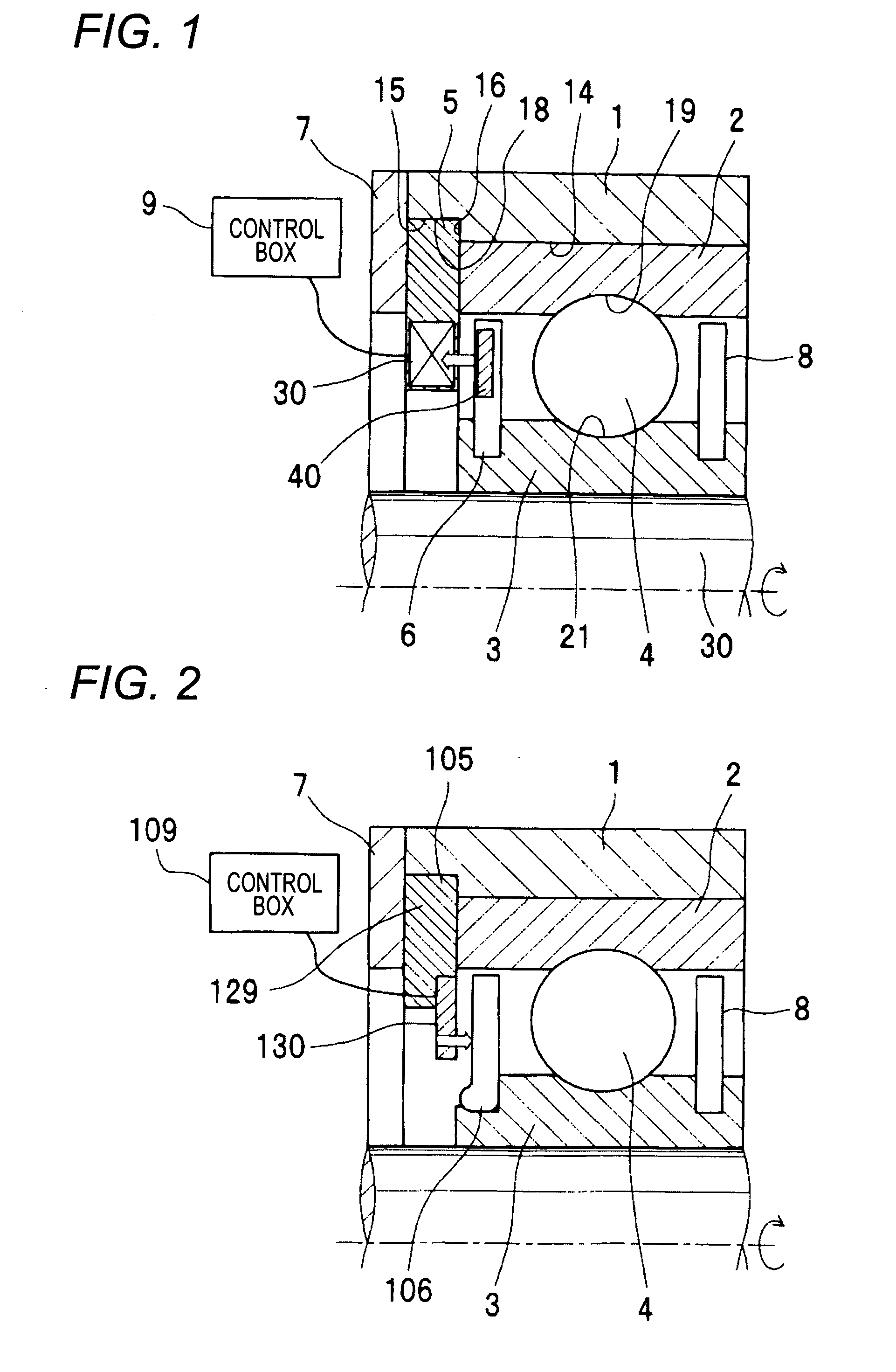
[0074]FIG. 2 is a schematic sectional view in an axial direction of a ball bearing apparatus according to the invention.

[0075]According to the ball bearing apparatus of the second embodiment, constituent portions the same as constituent portions of the ball bearing apparatus of the first embodiment are attached with the same reference numerals and an explanation thereof will be omitted. Further, according to the ball bearing apparatus of the second embodiment, an explanation of an operation and an effect and a modified example common to those of the ball bearing apparatus of the first embodiment will be omitted, and an explanation will be given only of a constitution, an operation, an effect and a modified example different from those of the ball bearing apparatus of the first embodiment.

[0076]The second embodiment differs from the first embodiment in that whereas a first portion 105 fixed to a first raceway member is not provided with an electromagnet, a piezoelectric element 130 i...

third embodiment

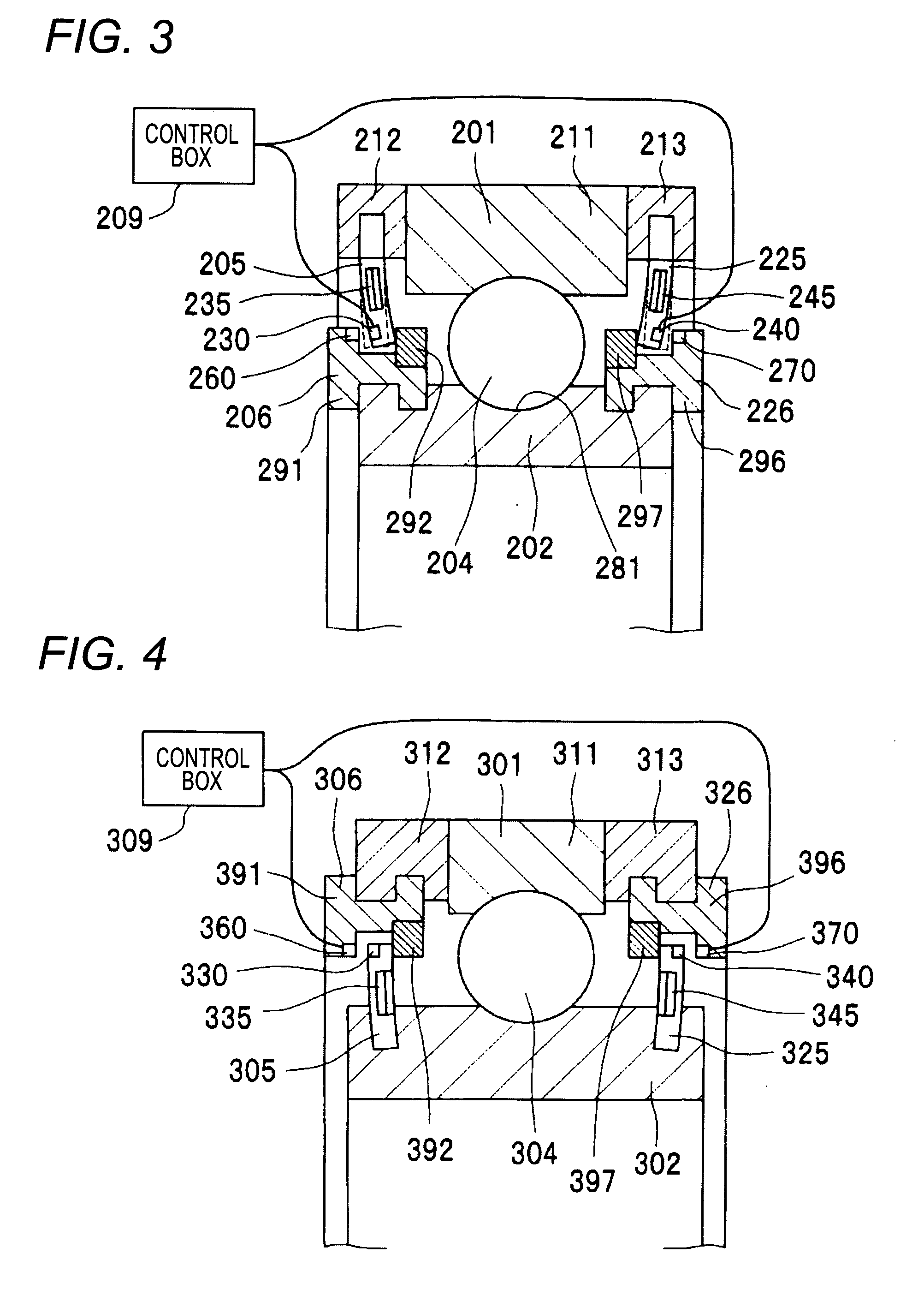
[0079]FIG. 3 is a schematic sectional view in an axial direction of a ball bearing apparatus according to the invention.

[0080]The ball bearing apparatus rotatably supports a main spindle of a machine tool, not illustrated. The ball bearing apparatus includes an outer ring 201 as a first raceway member, an inner ring 202 as a second raceway member, a plurality of balls 204, a first first portion 205, a second first portion 225, a first second portion 206, a second second portion 226, and a control box 209.

[0081]The outer ring 201 includes an outer ring main body 211 in a ring-like shape and substantially in a circular cylinder shape, a first sealing device fixing member 212 in a ring-like shape and substantially in a circular cylinder shape, and a second sealing device fixing member 213 in a ring-like shape and substantially in a circular cylinder shape. The first sealing device fixing member 212 is the same as the second sealing device fixing member 213. An end face on one side in a...


PUM

PropertyMeasurementUnit
temperatureaaaaaaaaaa
currentaaaaaaaaaa
conductiveaaaaaaaaaa

Abstract

First portions are fixed to an outer ring, and second portions are fixed to an inner ring. Bimetal members and electromagnets are embedded in and fixed by elastic portions of the first portions and portions of the second portions are constituted by ferromagnetic members. Whereas at a normal temperature region, the first portions and the second portions are brought into contact with each other, based on deformations of the bimetal members at a temperature equal to or higher than a predetermined temperature equal to or higher than the normal temperature region, the first portions and the second portions are made to be disposed to be spaced apart from each other by intervals therebetween at a temperature equal to or higher than the predetermined temperature equal to or higher than the normal temperature region.

Description

BACKGROUND OF THE INVENTION[0001]1. Field of the Invention[0002]The present invention relates to a sealing device, particularly, relates to a sealing device preferable when used for sealing an interval between an outer ring and an inner ring of a rolling bearing rotatably supporting a main spindle of a machine tool.[0003]Further, the invention relates to a rolling bearing apparatus including two race way members, a rolling element and a sealing device.[0004]2. Related Art[0005]In a background art, as a rolling bearing apparatus, there is a rolling bearing apparatus for a machine tool described in JP-A-2006-064106.[0006]The rolling bearing apparatus rotatably supports a main spindle of a machine tool. The rolling bearing apparatus includes an outer ring, an inner ring, a plurality of rolling elements, and seal members of covering openings on both sides in an axial direction between the outer ring and the inner ring.[0007]Whereas one end portion on an outer side in a diameter directio...

Claims


Application Information

Patent Timeline
Patent Type & Authority Applications(United States)
IPC IPC(8): F16C33/76F16J15/53F16J15/16F16C33/78
CPCF16C19/52F16C33/78F16J15/164Y10S277/919F16J15/445F16C41/00F16J15/3256F16C19/525F16C19/06F16C2322/39F16J15/3444
Inventor OTSUKA, KATSUNORIYAMAMOTO, TEKESHI
Owner JTEKT CORP
Why Eureka
Try Eureka