Reducer with internally meshing planetary gear mechanism and device incorporating the reducer

Inactive Publication Date: 2006-02-02
SUMITOMO HEAVY IND LTD
View PDF4 Cites 14 Cited by
  • Summary
  • Abstract
  • Description
  • Claims
  • Application Information

AI Technical Summary

Benefits of technology

[0018] The reducer with an internally meshing planetary gear mechanism and the device incorporating the reducer of the present invention can share many parts and components with c

Problems solved by technology

Contrary to the assumption that grease may simply be replaced by oil, however, the conventional reducer 10 with oil lubrication failed to achieve desired performance and product li

Method used


Image

  • Reducer with internally meshing planetary gear mechanism and device incorporating the reducer
  • Reducer with internally meshing planetary gear mechanism and device incorporating the reducer
  • Reducer with internally meshing planetary gear mechanism and device incorporating the reducer

Examples


Embodiment Construction

[0025] Preferred exemplary embodiments of the device incorporating a reducer with an internally meshing planetary gear mechanism of the invention will be hereinafter described with reference to the drawings.

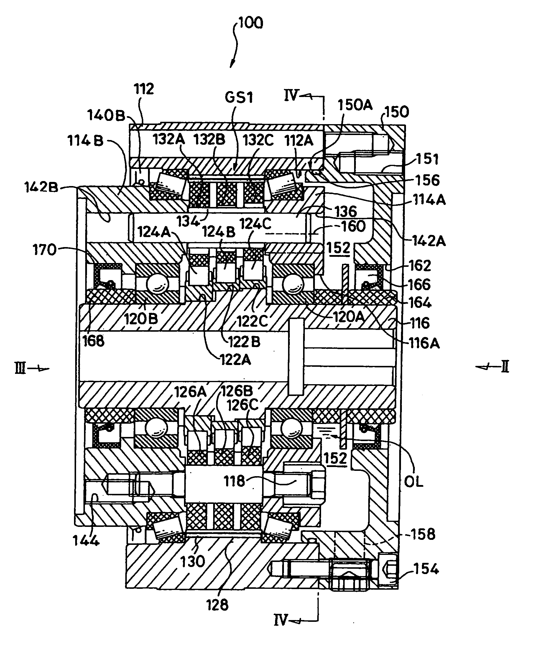
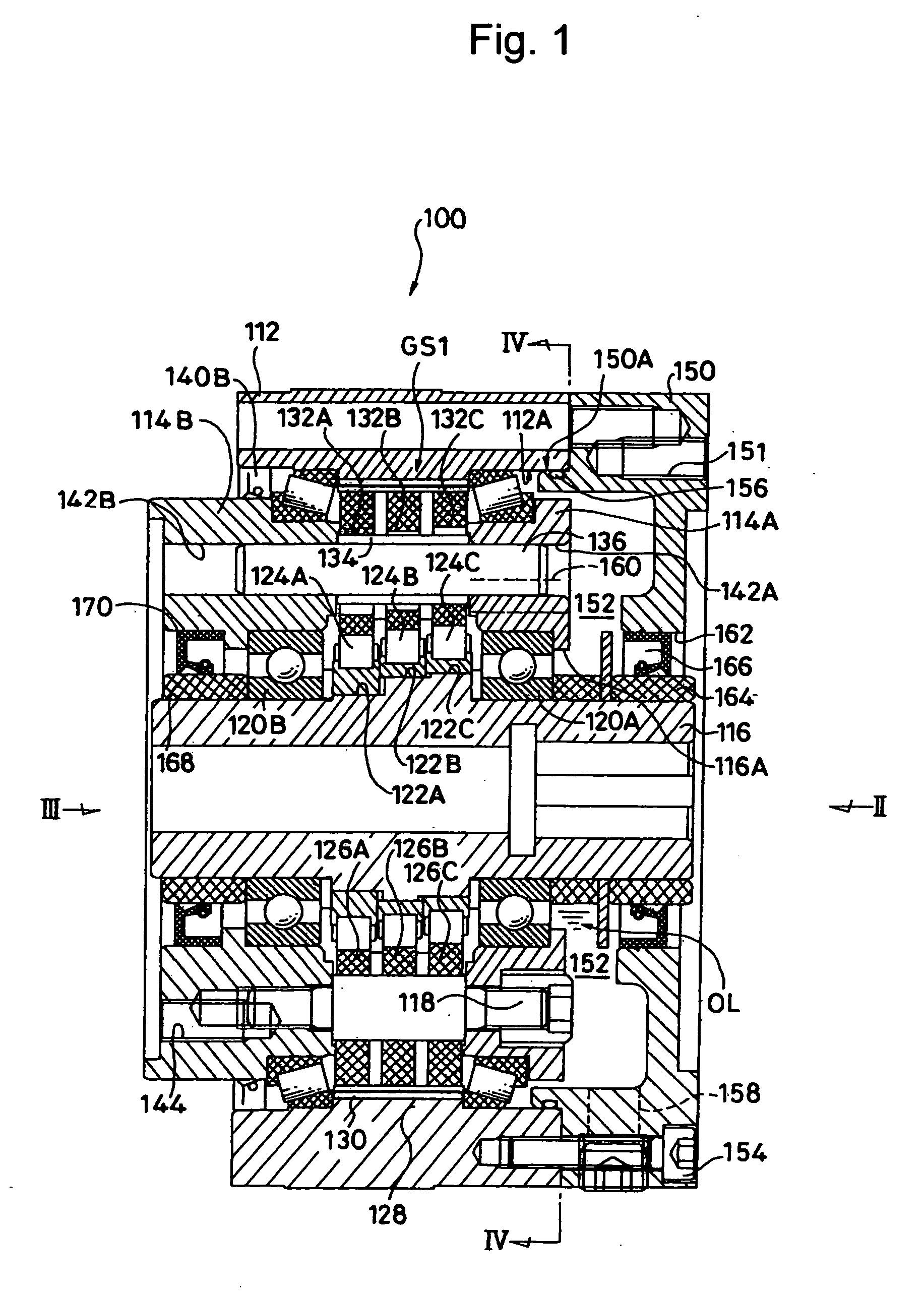
[0026]FIG. 1 is a cross-sectional view showing one exemplary embodiment of a device having a reducer with an internally meshing planetary gear mechanism (hereinafter simply referred to as “reducer device”) 100. FIG. 2 and FIG. 3 are side views taken from the directions of the arrows II and III in FIG. 1, respectively. FIG. 4 is a cross-sectional view taken along the line IV-IV in FIG. 1.

[0027] This reducer device 100 comprises a first flange 114A and a second flange 114B, and an internally meshing planetary reduction gear part (hereinafter simply referred to as “reduction gear part”) GS1. The first and second flanges 114A and 114B are disposed opposite each other inside a casing 112 and supported rotatably in the casing 112. The reduction gear part GS1 is disposed between the f...


PUM


Abstract

The device includes a cover coupled to a first flange on the opposite side from an internally meshing planetary reduction gear part. The cover has a hole through which the input shaft of the reduction gear extends. An oil reservoir section is formed between the cover and the first flange. Oil seals are provided between the input shaft and the cover, and between the input shaft and a second flange, respectively.

Description

BACKGROUND OF THE INVENTION [0001] 1. Field of the Invention [0002] The present invention relates to a reducer with an internally meshing planetary gear mechanism and a device incorporating the reducer used for driving a machine in a high-precision control system, such as a joint controller of industrial robots, an automatic tool exchanger, and the like. [0003] 2. Description of the Related Art [0004]FIG. 6 shows one example of a conventional reducer with an internally meshing planetary gear mechanism (hereinafter simply referred to as “reducer”) 10 used for driving a machine in a high-precision control system, such as a joint controller of industrial robots or an automatic tool exchanger (Japanese Patent Laid-Open Publication No. 2001-187945). The reducer 10 is provided with a first flange 14A and a second flange 14B, and an internally meshing planetary reduction gear part (hereinafter simply referred to as “reduction gear part”) GS0. The first and second flanges 14A and 14B are di...

Claims


Application Information

Patent Timeline
IPC IPC(8): F16H57/04F16H57/02
CPCF16H1/32F16H57/0486F16H57/0457
Inventor EGAWA, MASANORI
Owner SUMITOMO HEAVY IND LTD
Why Eureka
Try Eureka