Cryopump with two-stage pulse tube refrigerator

a technology of cryopump and pulse tube, which is applied in the field of cryocoolers, can solve the problems of system significantly more vibration, production defects, and most vacuum chamber processes are very sensitive to vibration

Inactive Publication Date: 2006-02-09
SHI APD CRYOGENICS +1
View PDF7 Cites 21 Cited by
  • Summary
  • Abstract
  • Description
  • Claims
  • Application Information

AI Technical Summary

Problems solved by technology

Most military type applications use Stirling pulse tubes that operate at frequencies of 20 to 60 Hz, and as a result of the high speed are small, but are limited to temperatures above about 20 K. Cryogenic temperatures as cold as 3 K are achievable using two stage GM type pulse tube refrigerators which typically operate at 1 to 2 Hz.
Most vacuum chamber processes are very sensitive to vibration.
With processes requiring accuracy to within nanometers, any motion can result in production defects.
Conventional refrigerators used for obtaining these low temperatures are Gifford McMahon, GM, cycle systems, however, these systems have significantly more vibration than a pulse tube.
Multistage pulse tube coolers of the prior art reject all the heat from each successively lower-temperature pulse tube cooler to the preceding higher-temperature pulse tube cooler, thus imposing a large cooling load on the higher-temperature pulse tube coolers which considerably reduces the overall efficiency of the cooler.

Method used


Image

  • Cryopump with two-stage pulse tube refrigerator
  • Cryopump with two-stage pulse tube refrigerator
  • Cryopump with two-stage pulse tube refrigerator

Examples


first embodiment

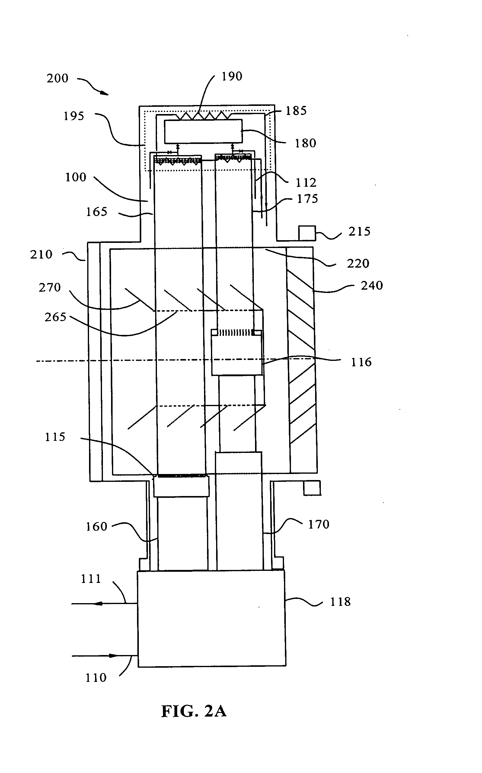
[0041]FIGS. 2a, 2b, and 2c, illustrate a side-view, top view, and an end view respectively, of a cryopump 200 including a gas supply 110, a gas return 111, a valve assembly 118, a first stage regenerator 160, a first stage pulse tube 165, a first stage cold station 115, a second stage regenerator 170, a second stage pulse tube 175, a second stage cold station 116, a hot end assembly 195, a housing 210, a flange 215, a first stage thermal shield 220, inlet louvers 240, and a second stage cryopanel 265. Cryopanel 265 further includes fins 270.

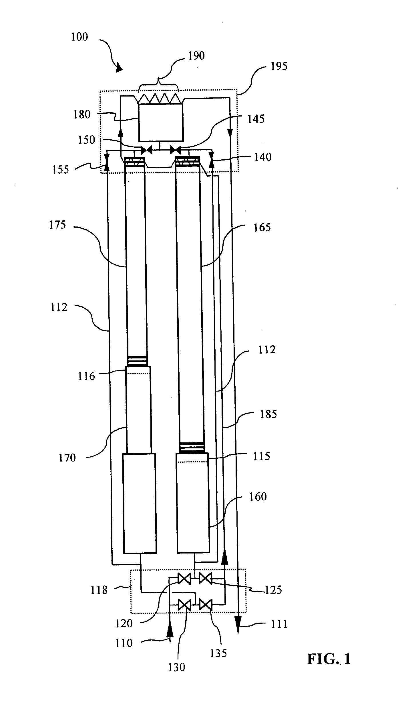
[0042] Valve assembly 118 includes active valves 120, 125, 130, and 135, shown in FIG. 1, along with a drive motor [not shown]. Gas supply 110 and gas return 111 are supply and return lines for providing a working gas (helium) within cryocooler 100. The gas supply and return lines are connected to a through flow type compressor.

[0043] Hot end assembly 195 includes the hot ends of pulse tubes 165 and 175, buffer tank 180, fixed orifices 140, 145,...

second embodiment

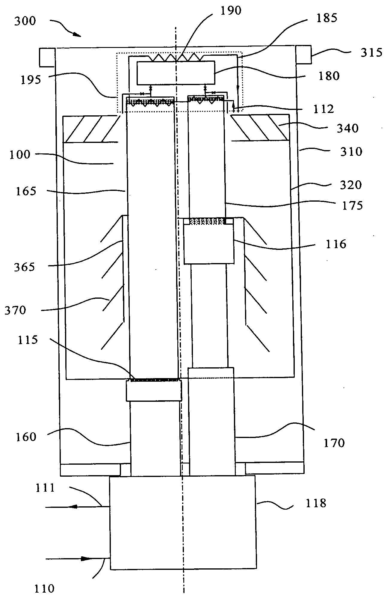
[0053]FIG. 3 illustrates the invention, where the element numbers are identified as described above.

[0054] The refrigeration systems of FIGS. 2 and 3 operate on the same principle but are configured in two different orientations. Because the pulse tube has to be operated with the hot end on top, it has to be mounted nearly vertically. A side inlet pump is shown in FIG. 2; a top inlet pump is shown in FIG. 3.

[0055] The side inlet pump, FIG. 2, is more effective because the hot end can be further from the cold panels than the top inlet design, FIG. 3. Furthermore, it is easier to get the cold inlet louver 240 closer to the flange, so the pumping speed will be higher for the side inlet pump than the top inlet pump. Pumping speed for the top inlet pump is also reduced because the hot end of the pulse tube blocks some of the flow.

[0056] Cryopump 300 includes a housing 310, a flange 315, a first stage thermal shield 335, inlet louvers 340, and a second stage cryopanel 365. Cryopanel 365...


PUM

PropertyMeasurementUnit
Cryogenic temperaturesaaaaaaaaaa

Abstract

Disclosed is a two-stage pulse tube cryopump cooling system in which the pulse tubes and valves are inline, with the hot ends of the pulse tubes at the top and the valve mechanism is at the bottom and the hot ends and buffer volume are cooled by an inline coolant line from the compressor input to the compressor output and attached in heat exchange relationship with the buffer volume.

Description

[0001] This application claims the benefit of U.S. Provisional Application No. 60 / 346,512, filed Jan. 8, 2002.BACKGROUND OF THE INVENTION [0002] The pulse tube refrigerator is a cryocooler, similar to Stirling and Gifford-McMahon refrigerators, which derive cooling from the compression and expansion of gas. However, unlike the Stirling and Gifford-McMahon (G-M) systems, in which the gas expansion work is transferred out of the expansion space by a solid expansion piston or displacer, pulse tube refrigerators have no moving parts in their cold end, but rather an oscillating gas column within the pulse tube (called a gas piston) that functions as a compressible displacer. The elimination of moving parts in the cold end of pulse tube refrigerators allows a significant reduction of vibration, as well as greater reliability and lifetime, and is thus potentially very useful in many applications, both military and commercial. [0003] Most military type applications use Stirling pulse tubes ...

Claims


Application Information

Patent Timeline
Patent Type & Authority Applications(United States)
IPC IPC(8): F25B9/00B01D8/00F25B9/14
CPCF25B9/006F25B9/10F25B9/145F25B2309/1407F25B2309/1412F25D19/006F25B2309/1421F25B2309/14241F25B2309/1425F25B2309/1427F25B2500/17F25B2309/1418
Inventor GAO, JIN LIN
Owner SHI APD CRYOGENICS
Why Eureka
Try Eureka