Hydrometer/fluid level sensor

Inactive Publication Date: 2006-02-09
ILLINOIS TOOL WORKS INC
View PDF9 Cites 8 Cited by
  • Summary
  • Abstract
  • Description
  • Claims
  • Application Information

AI Technical Summary

Benefits of technology

[0011] An advantage of the present invention is providing a light transmissive body for a battery condition indicator that is stronger than known light transmissive bodies.
[0012] Another advantage of the present invention is providing a light transmissive body for a fluid condition indicator that exhibits a more discernable visual queue.
[0013] Still another advantage of the present

Problems solved by technology

The small diameter visual queue can be difficult to perceive accurately, and requires users to understand a color code system of indicated conditions.
Rod-shaped transmissive bodies can be damaged during handling, before installation in a battery.
A small, hair-line crack that is undetected before installation can propagate over time, causing the indicator to fail in the battery.
Injecting plastic into a rod-shaped form can be difficult.
If

Method used


Image

  • Hydrometer/fluid level sensor
  • Hydrometer/fluid level sensor

Examples


Embodiment Construction

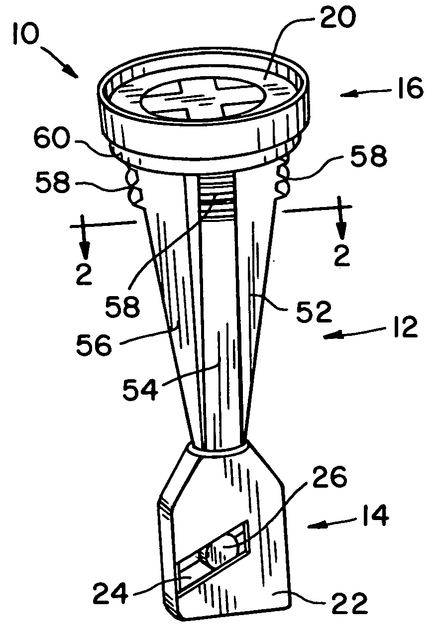
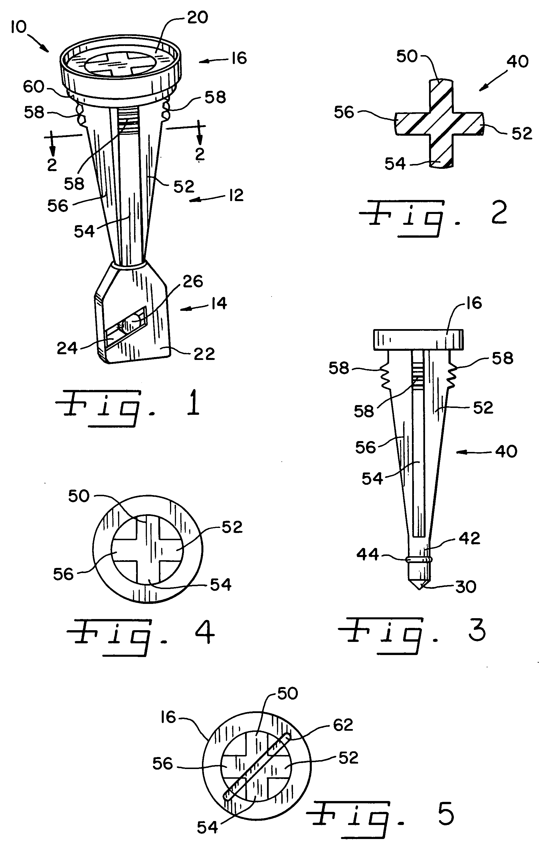
[0021] Referring now more specifically to the drawings and to FIG. 1 in particular, numeral 10 designates a fluid condition indicator, and, more specifically, a battery electrolyte condition indicator having a light transmissive body 12 in accordance with the present invention. Light transmissive body 12 is disposed between a response assembly 14 and an indicator head 16.

[0022] Indicators of the type to be described can be used in vessels or containers other than lead / acid storage batteries, although the use in such batteries is a particularly advantageous use thereof. Indicators 10 can be used to detect fluid level changes in a variety of containers or vessels and may also be used to detect changes in other fluid conditions.

[0023] Indicator head 16 defines a window 20 for peering into indicator 10. Head 16 can be a single piece of clear plastic or the like, and can be formed as a monolithic body with light transmissive body 12.

[0024] Response assembly 14 is connected to light tr...


PUM


Abstract

A light transmissive body for a fluid condition indicator has a substantial length shaped as a cruciform in transverse cross-section.

Description

CROSS-REFERENCE TO RELATED APPLICATIONS [0001] The present United States patent application claims the benefits of U.S. Provisional Application Ser. No. 60 / 599,796 filed Aug. 6, 2004.FIELD OF THE INVENTION [0002] I The present invention relates generally to hydrometers and fluid level sensors in storage batteries; and, more particularly, the invention pertains to the light transmissive body between the responsive assembly immersed in the battery fluid and the indicator head along the outer surface of the battery. BACKGROUND OF THE INVENTION [0003] Battery condition indicators are used in lead / acid storage batteries of many types, including those installed in motor vehicles. Known battery condition indicators function as hydrometers detecting changes in the specific gravity indicative of the electric charge condition of the battery and provide a visual indication of the charge condition. Battery condition indicators also can detect changes in electrolyte level of the battery and prov...

Claims


Application Information

Patent Timeline
IPC IPC(8): G01F23/00
CPCH01M10/484H01M10/06Y02E60/10
Inventor SUMMER, MARK J.WITT, MARTIN A.
Owner ILLINOIS TOOL WORKS INC
Why Eureka
Try Eureka