Magnetic field protection for the projectile of an electromagnetic coil gun system

a technology of electromagnetic coil and projectile, which is applied in the direction of weapons, launching weapons, white arms/cold weapons, etc., can solve the problems of large amount of magnetic shielding for the extremely high magnetic field produced by the launcher, and the range of the launcher is not large enough, so as to reduce the propulsive force, and increase the magnitude of the null magnetic field

Active Publication Date: 2006-02-09
RAYTHEON CO
View PDF9 Cites 16 Cited by
  • Summary
  • Abstract
  • Description
  • Claims
  • Application Information

AI Technical Summary

Benefits of technology

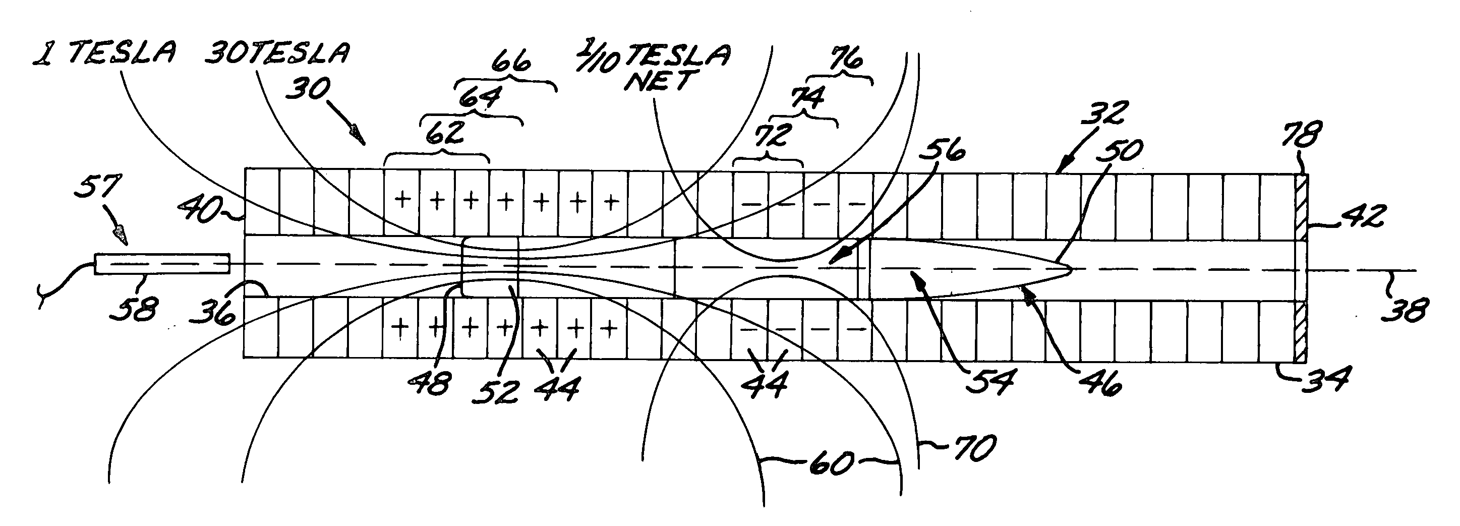
[0014] The present approach at least partially nullifies the traveling propulsive magnetic field in the region of the nose of the projectile, where the guidance subsystem and other magnetic-field-sensitive components are located. However, the nulling magnetic field also negates the traveling propulsive magnetic field to some extent, thereby reducing the propulsive force applied when the projectile is fired. The greater the magnitude of the nulling magnetic field, the more the propulsive force is reduced. Consequently, it is preferred that the magnitude of the nulling magnetic field not be so large as to completely cancel the traveling propulsive magnetic field near the nose of the projectile. Instead, the traveling propulsive magnetic field near the nose of the missile is partially canceled, and a small amount of conventional magnetic shielding is used to protect the guidance subsystem and other sensitive components from the residual magnetic field near the nose of the projectile. Because there is no armature in the projectile near the nose end of the projectile, the adverse effect of the nulling magnetic field in reducing the projectile force and velocity is minimal.
[0015] In the preferred embodiment of the present approach, the same electrical excitation coils that produce the traveling propulsive magnetic field also produce the traveling nulling magnetic field. This allows the efficient use of the launcher structure, which is utilized in each firing of a projectile. Additional capacitors and electrical circuitry are required for the launcher to generate the field-nulling currents, but these are a permanent part of the launcher structure and are not consumables. The projectile is modified by reducing the magnetic shielding that is required, allowing the payload to have more weight and volume than would otherwise be the case.

Problems solved by technology

These guidance technologies are all susceptible to erratic behavior or failure as a result of the high-magnetic-field environment, typically 30 Teslas or greater, produced within the launcher barrel during the firing of the projectile.
This approach has the drawback that a sufficient amount of magnetic shielding for the extremely high magnetic fields produced by the launcher must be quite thick and consequently heavy.

Method used


Image

  • Magnetic field protection for the projectile of an electromagnetic coil gun system
  • Magnetic field protection for the projectile of an electromagnetic coil gun system
  • Magnetic field protection for the projectile of an electromagnetic coil gun system

Examples


Embodiment Construction

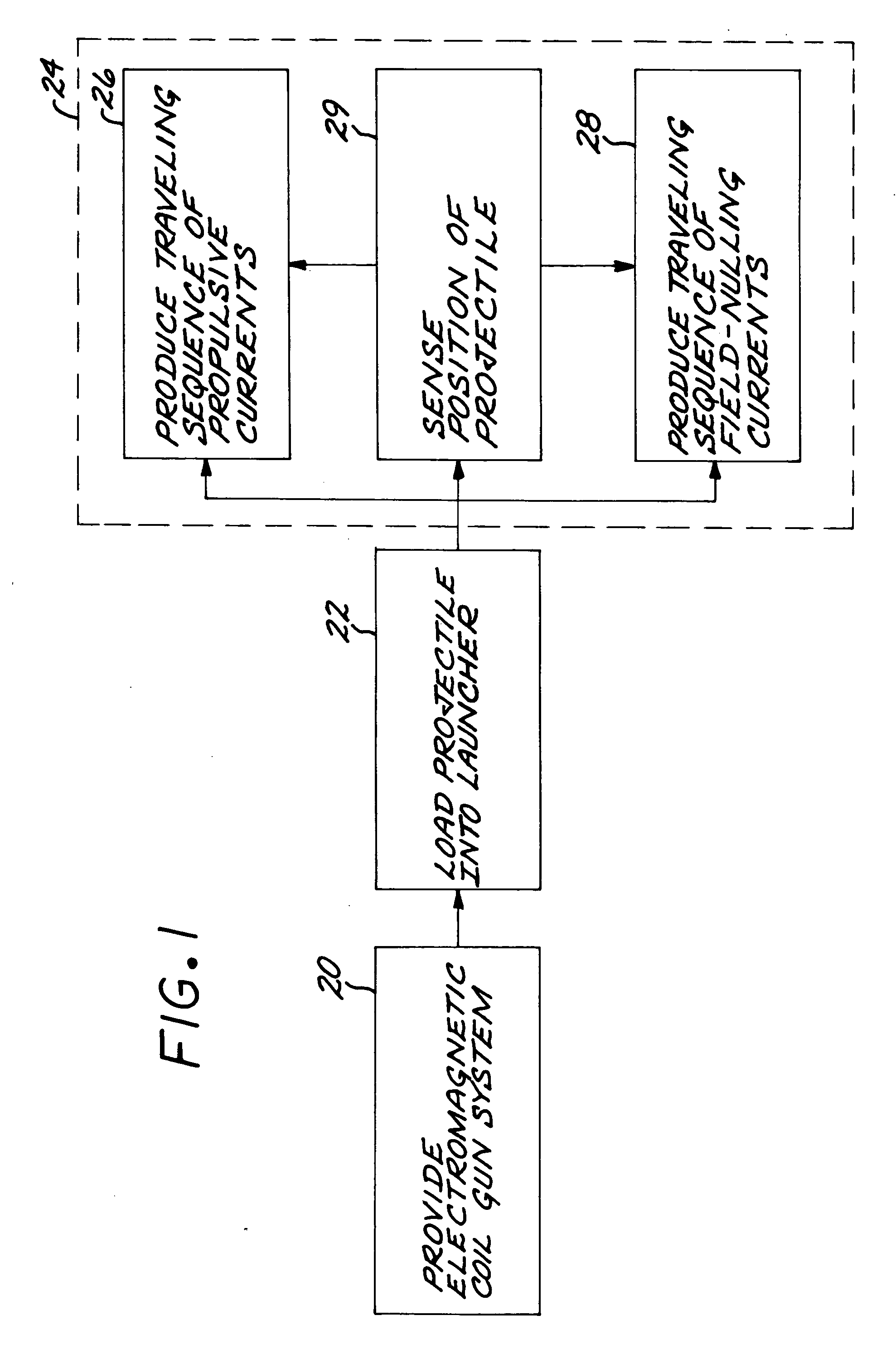
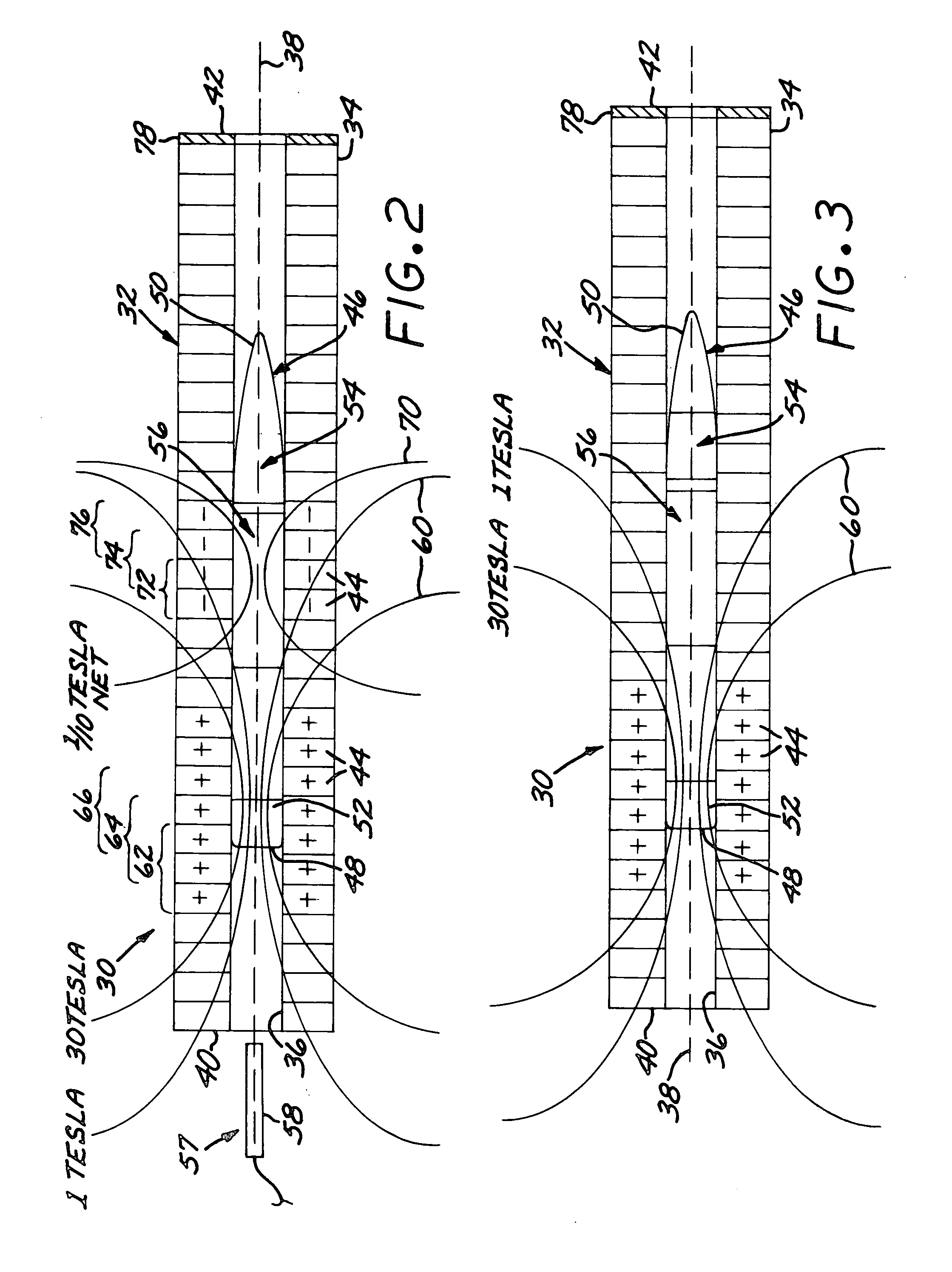
[0023]FIG. 1 depicts an embodiment of a method for operating an electromagnetic coil gun system, and FIG. 2 schematically illustrates an electromagnetic coil gun system 30. The electromagnetic coil gun system 30 is provided, step 20. The electromagnetic coil gun system 30 includes a launcher 32, which includes a barrel 34 having a longitudinal bore 36 therethrough. The barrel 34 and bore 36 are generally cylindrically symmetrical about a centerline 38. (The longitudinal direction is parallel to the centerline 38.) The barrel 34 may be described as having a breech end 40 and a muzzle end 42. The launcher 32 further includes a plurality of longitudinally extending electrical excitation coils 44 arranged circumferentially around the bore 36 of the barrel 34. A magnetic field produced by an electrical current flowing in each electrical excitation coil 44 penetrates into the bore 36. Each electrical excitation coil 44 is independently activated by the electrical current passed therethrou...


PUM


Abstract

An electromagnetic coil gun system includes a launcher having a barrel with a longitudinal bore therethrough, and a plurality of longitudinally extending electrical excitation coils arranged circumferentially around the bore of the barrel so that a magnetic field produced by an electrical current in each electrical excitation coil penetrates into the bore. Each electrical excitation coil is independently activated by the electrical current passed therethrough. There is a projectile sized to be received within the bore of the barrel and having a circumferential armature at a tail end thereof, and a nose end. The projectile placed into the bore is fired by producing a traveling sequence of propulsive currents in the electrical excitation coils moving in a direction from the breech end toward the muzzle end of the barrel, so that a traveling propulsive magnetic field produced by the electrical excitation coils interacts with the armature of the projectile to propel the projectile in the direction from the breech end toward the muzzle end of the barrel. Simultaneously, a traveling sequence of field-nulling currents in the electrical excitation coils moves in the direction from the breech end toward the muzzle end of the barrel but closer to the muzzle end of the barrel than the traveling sequence of propulsive currents and spatially leading the traveling sequence of propulsive currents. The field-nulling currents are in a circumferential direction opposite to the propulsive currents, thereby at least partially nulling the traveling propulsive magnetic field at the nose end of the projectile.

Description

[0001] This invention relates to an electromagnetic coil gun system, and more particularly to such a system wherein the projectile has magnetic-field sensitive electronics therein. BACKGROUND OF THE INVENTION [0002] An electromagnetic coil gun system includes a launcher and a projectile that is fired from the launcher. The launcher has a barrel with a series of circumferential electrical excitation coils that extend longitudinally along the length of the barrel. The projectile has a circumferential armature near its tail. The projectile is propelled from the gun by producing a traveling sequence of propulsive currents in the electrical excitation coils. A propulsive magnetic field produced by the electrical excitation coils interacts with the armature of the projectile to propel the projectile along the length of the barrel and out of the muzzle end of the barrel. The fundamental principles of the electromagnetic coil gun have been known for some time, see for example U.S. Pat. Nos....

Claims


Application Information

Patent Timeline
Patent Type & Authority Applications(United States)
IPC IPC(8): F41B6/00
CPCF41B6/003
Inventor SCHNEIDER, ARTHUR J.
Owner RAYTHEON CO
Why Eureka
Try Eureka