Downhole rotary drilling apparatus with formation-interfacing members and control system

a technology of formation interface and control system, which is applied in the direction of drilling pipes, directional drilling, artificial islands, etc., can solve the problems of limited run time, inability to easily separate the interface between the control system and the conventional system, and limited run time, so as to improve the stability, reduce the force needed to push the bit, and enhance the steering ability

Inactive Publication Date: 2015-04-28
NAT OILWELL VARCO LP
View PDF265 Cites 13 Cited by
  • Summary
  • Abstract
  • Description
  • Claims
  • Application Information

AI Technical Summary

Benefits of technology

[0021]Preferably, the steering section of the drill bit is demountable from the control assembly (such as by means of a conventional pin-and-box threaded connection), with the rotating upper plate being incorporated into the control assembly. This facilitates field assembly of the components to complete the RSS tool at the drilling rig site, and facilitates quick drill bit changes at the rig site, either to use a different cutting structure, or to service the steering section, without having to remove the control assembly from the drill string.
[0025]By having a side force applied directly at the drill bit, close to the cutting structure, rather than at a substantial distance above the bit as in conventional push-the-bit systems, bit steerability is enhanced, and the force needed to push the bit is reduced. Lower side forces at the bit, with a bit that is kept in line with the rest of the stabilized drill string behind, also increases stability and enhances repeatability in soft formations. The term “repeatability”, as used in this patent specification, is understood in the directional drilling industry as denoting the ability to repeatably achieve a consistent curve radius (or “build rate”) for the trajectory of a wellbore in a given subsurface formation, independent of the strength of the formation. The greater the magnitude of the force applied against the wall of a wellbore by a piston in a push-the-bit drilling system, the greater will be the tendency for the piston to cut into softer formations and reduce the curvature of the trajectory of the wellbore (as compared to the effect of similar forces in harder formations). Accordingly, this tendency in softer formations will be reduced by virtue of the lower piston forces required for equal effectiveness when using push-the-bit systems in accordance with the present disclosure.
[0026]Push-the-bit rotary steerable drilling systems and apparatus in accordance with the present disclosure may be of modular design, such that any of the various components (e.g., pistons, reaction members, control assembly, and control assembly components) can be changed out in the field during bit changes. As previously noted, another advantageous feature of the apparatus is that the rotating upper plate (or sleeve) of the fluid-metering assembly can be deactivated such that the tool will drill straight when deviation of the wellbore is not required, thereby promoting longer battery life (e.g., for battery-powered control assembly components) and thus extending the length of time that the tool can operate without changing batteries.

Problems solved by technology

Most of these conventional systems are complex and expensive, and have limited run times due to battery and electronic limitations.
Currently there is no easily separable interface between RSS control systems and formation-interfacing reaction members that would allow directional control directly at the bit.
Push-the-bit systems are simpler and more robust, but have limitations due to the applied side force being several feet from the bit and thus requiring the application of comparatively large forces to deflect the bit.
Currently-used RSS designs typically require large pressure drops across the bit, thus limiting hydraulic capabilities in a given well due to increased pumping horsepower requirements for circulating drilling fluid through the apparatus.
Point-the-bit systems may offer performance advantages over push-the-bit systems, but they require complex and expensive drill bit designs; moreover, they can be prone to bit stability problems in the wellbore, making them less consistent and harder to control, especially when drilling through soft formations.
Should large debris (e.g., rocks) or large quantities of lost circulation material (e.g., drilling fluid) be allowed to enter the valve arrangements in current push-the-bit tool designs, valve failure is typically the result.
However, filter subs are also prone to problems; should lost circulation material or rocks enter and plug up a filter sub, it may be necessary to remove (or “trip”) the drill string and bit from the wellbore in order to clean out the filter.
This results in increased costs and lost time associated with bit changes.

Method used


Image

  • Downhole rotary drilling apparatus with formation-interfacing members and control system
  • Downhole rotary drilling apparatus with formation-interfacing members and control system
  • Downhole rotary drilling apparatus with formation-interfacing members and control system

Examples


Embodiment Construction

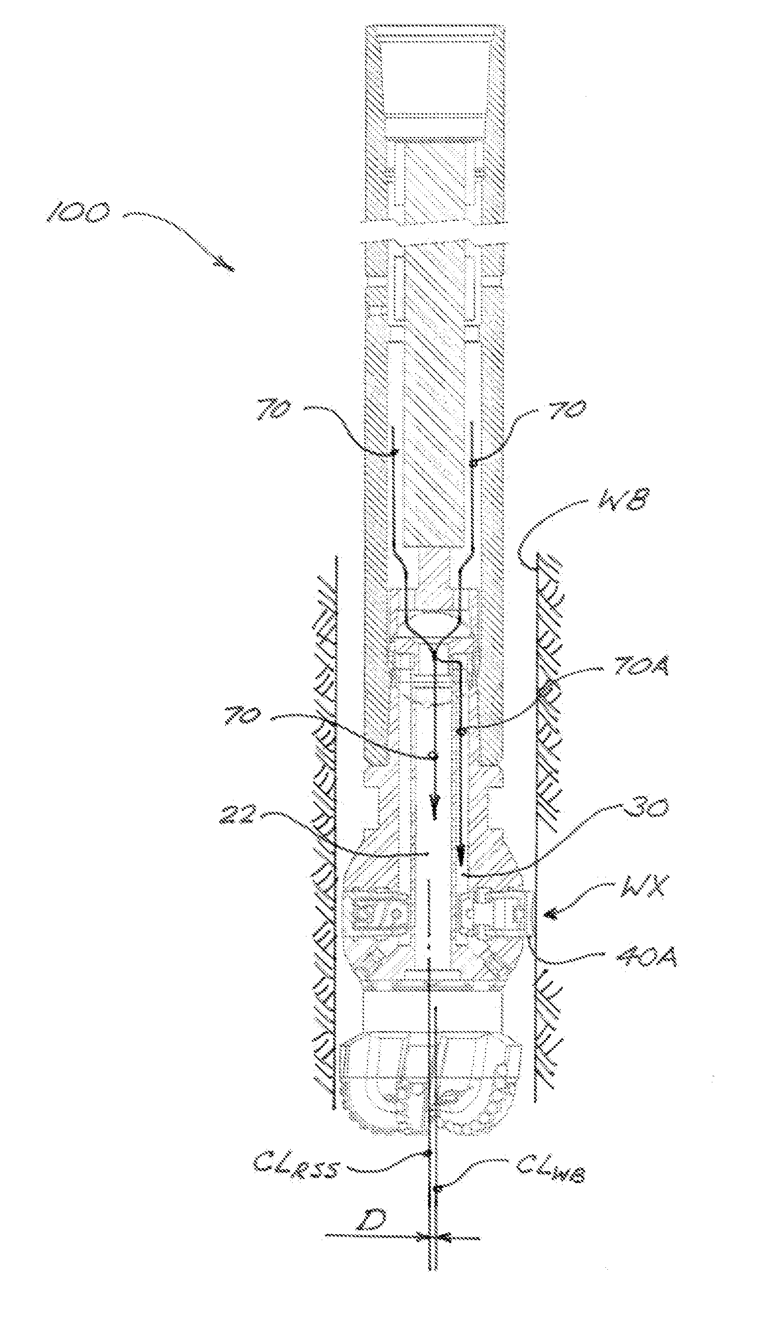
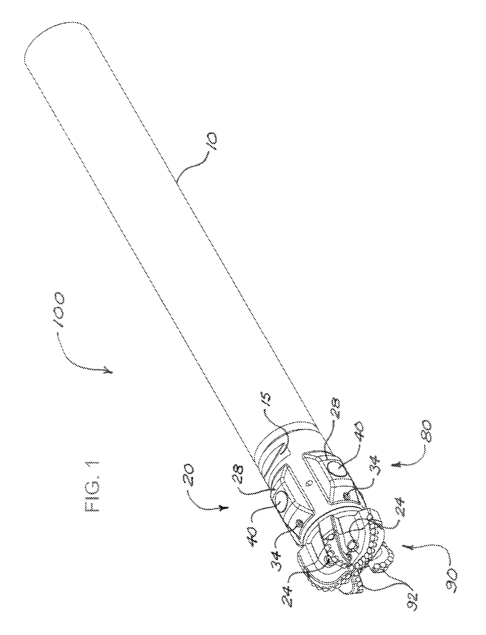
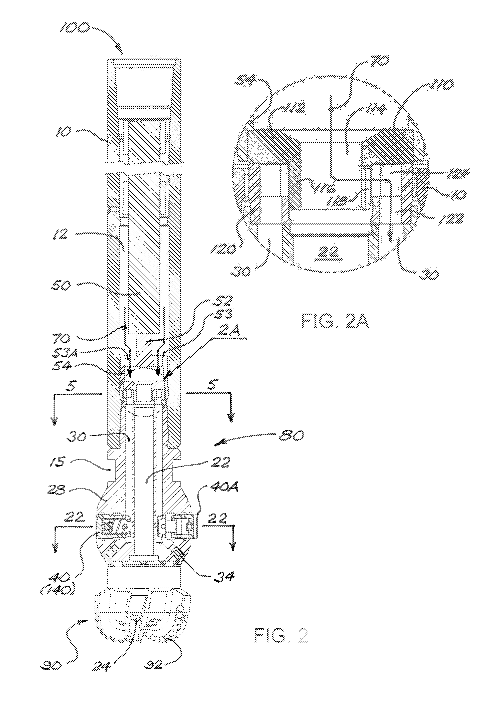
[0070]FIGS. 1 and 2 illustrate (in isometric and cross-sectional views, respectively) a rotary steerable drilling apparatus (or “RSS tool”) 100 in accordance with a first embodiment. RSS tool 100 comprises a cylindrical housing 10, which encloses a control assembly 50; and a drill bit 20. An annular space 12 is formed around control assembly 50 within housing 10, such that drilling fluid flowing into housing 10 will flow downward through annular space 12 toward drill bit 20. Drill bit 20 comprises a steering section 80 connected to the lower end of housing 10, and a cutting structure 90 connected to the lower end of steering section 80 so as to be rotatable therewith. Steering section 80 is preferably formed or provided with means for facilitating removal from housing 10, such as bit breaker slots 15. Cutting structure 90 may of any suitable type (for example, a polycrystalline diamond compact bit or a roller-cone-style bit), and cutting structure 90 does not form part of the broade...


PUM


Abstract

A steerable drilling apparatus includes a control system inside a cylindrical housing connected to a drill bit having radially-extendable pistons. A fluid-metering assembly directs a piston actuating fluid into fluid channels in the drill bit leading to respective pistons. The control system controls the fluid-metering assembly to selectively allow fluid flow through the fluid channels to the pistons and to exit through orifices in the fluid channels. The selective fluid flow causes the actuated piston to temporarily extend in the opposite direction to a desired wellbore deviation, thereby deflecting the drill bit away from the borehole centerline. An upper member in the fluid-metering assembly can be moved to stabilize, steer, and change TFA within the drill bit. The control system and drill bit are connected so as to facilitate removal to change the drill bit's steering section and cutting structure configuration or gauge simultaneously.

Description

CROSS-REFERENCE TO RELATED APPLICATIONS[0001]This application claims the benefit of U.S. Provisional Application No. 61 / 381,243 , filed on Sep. 9, 2010 , and U.S. Provisional Application No. 61 / 410,099 , filed on Nov. 4, 2010 , and said earlier applications are incorporated herein by reference in their entirety for continuity of disclosure.FIELD OF THE DISCLOSURE[0002]The present disclosure relates in general to systems and apparatus for directional drilling of wellbores, particularly for oil and gas wells.BACKGROUND[0003]Rotary steerable systems (RSS) currently used in drilling oil and gas wells into subsurface formations commonly use tools that operate above the drill bit as completely independent tools controlled from the surface. These tools are used to steer the drill string in a desired direction away from a vertical or other desired wellbore orientation, such as by means of steering pads or reaction members that exert lateral forces against the wellbore wall to deflect the dr...

Claims


Application Information

Patent Timeline
Patent Type & Authority Patents(United States)
IPC IPC(8): E21B7/06E21B7/04E21B17/10
CPCE21B17/1014E21B7/06
Inventor CLAUSEN, JEFFERYPRILL, JONATHAN RYAN
Owner NAT OILWELL VARCO LP
Why Eureka
Try Eureka