Liquid heating apparatus and cleaning apparatus and method

a technology of cleaning apparatus and heating apparatus, which is applied in the direction of electrical apparatus, microwave heating, electric/magnetic/electromagnetic heating, etc., can solve the problems of reducing heating efficiency, unable to save space, and breaking of heater wires

Inactive Publication Date: 2006-02-09
PANASONIC CORP
View PDF1 Cites 19 Cited by
  • Summary
  • Abstract
  • Description
  • Claims
  • Application Information

AI Technical Summary

Benefits of technology

[0048] In the step (b), a second type of microwaves with a different frequency from that of the first type of microwaves may be applied to the liquid in the reservoir. Therefore, a large amount of liquid can be heated or a liquid can be heated at high speed. The shift of the frequency of the first type of microwaves from that of the second type of microwaves can prevent the two microwaves from canceling each other.

Problems solved by technology

Furthermore, deterioration of the heater wire 113 itself over time may also cause the breakage of the heater wire 113 due to the abnormal heating and a break thereof and simultaneously the breakage of the heater tube 112.
This has reduced the heating efficiency.
Furthermore, since a heating apparatus cannot be installed in a cleaning apparatus dealing with a volatile chemical solution and thus need be installed outside the cleaning apparatus, space could not be saved.
However, it is difficult to reduce the flow rate of the cleaning solution, because the performance of the cleaning apparatus is decreased.
However, since a high-power microwave heating apparatus is very expensive, it is practically difficult to employ the high-power microwave heating apparatus.

Method used


Image

  • Liquid heating apparatus and cleaning apparatus and method
  • Liquid heating apparatus and cleaning apparatus and method
  • Liquid heating apparatus and cleaning apparatus and method

Examples


embodiment 1

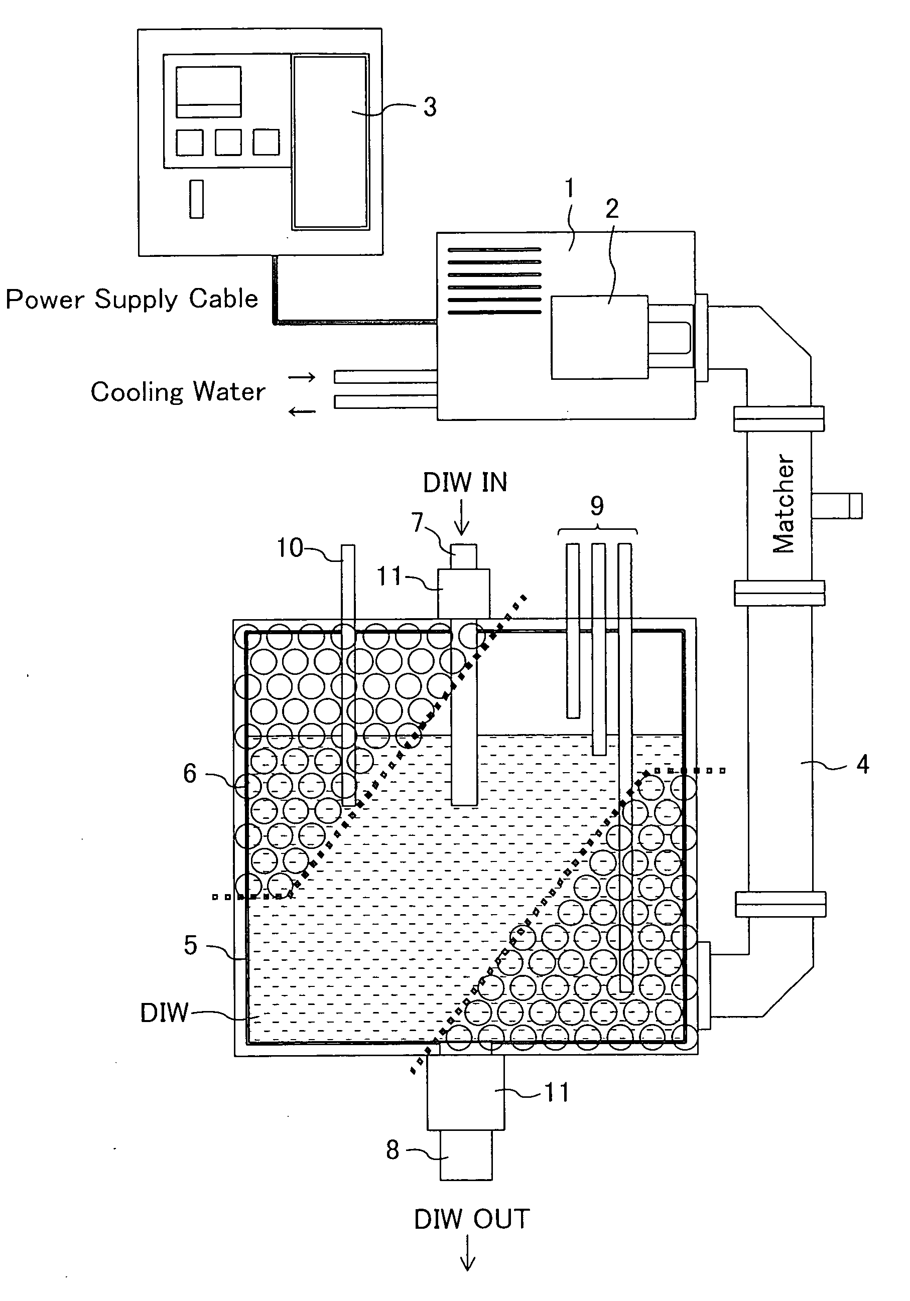
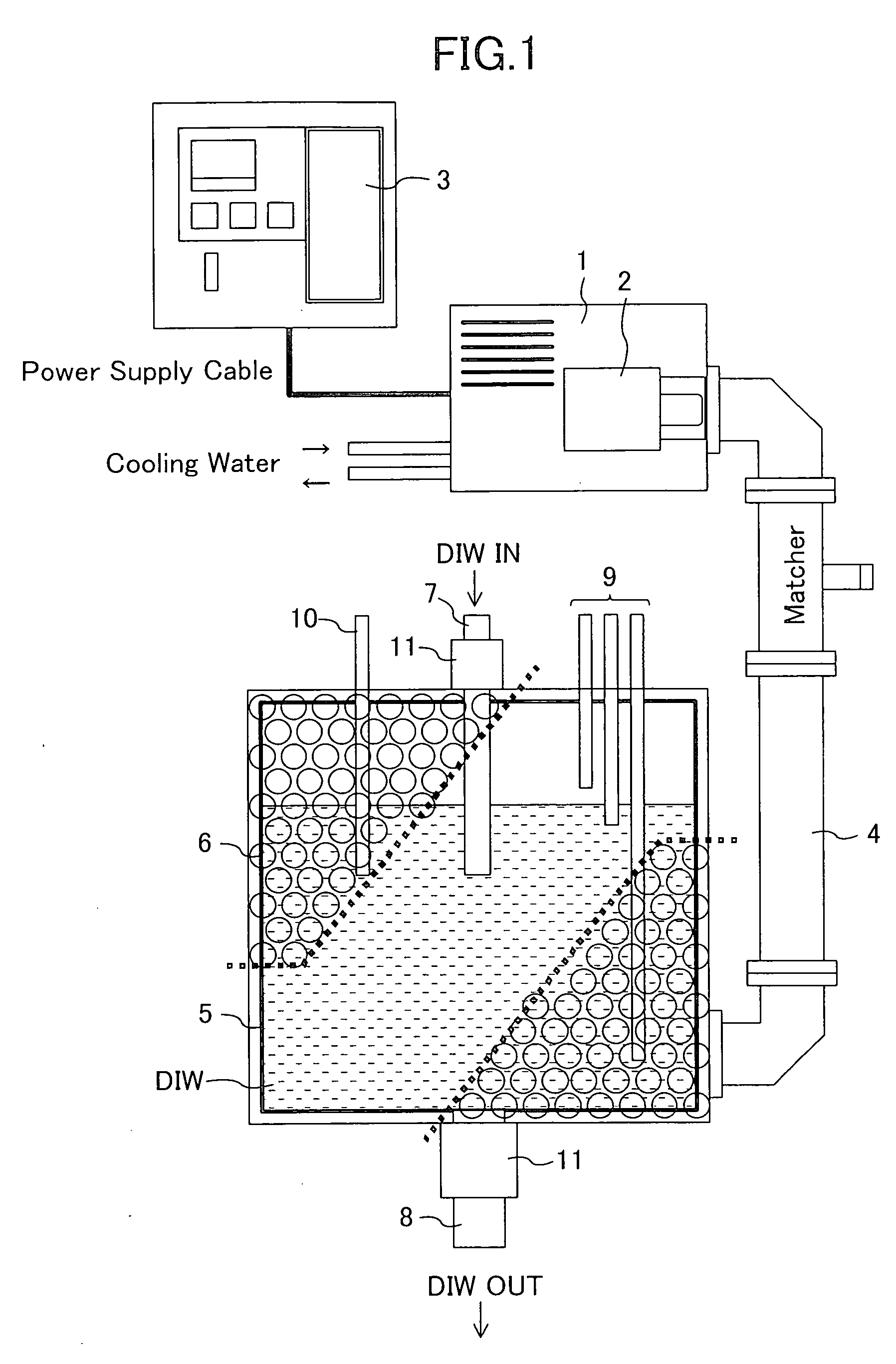
[0062]FIG. 1 is a schematic view showing an example of a hot water production apparatus according to a first embodiment of the present invention. This hot water production apparatus is used to produce hot water for preparing, for example, a high-temperature cleaning solution for semiconductor devices.

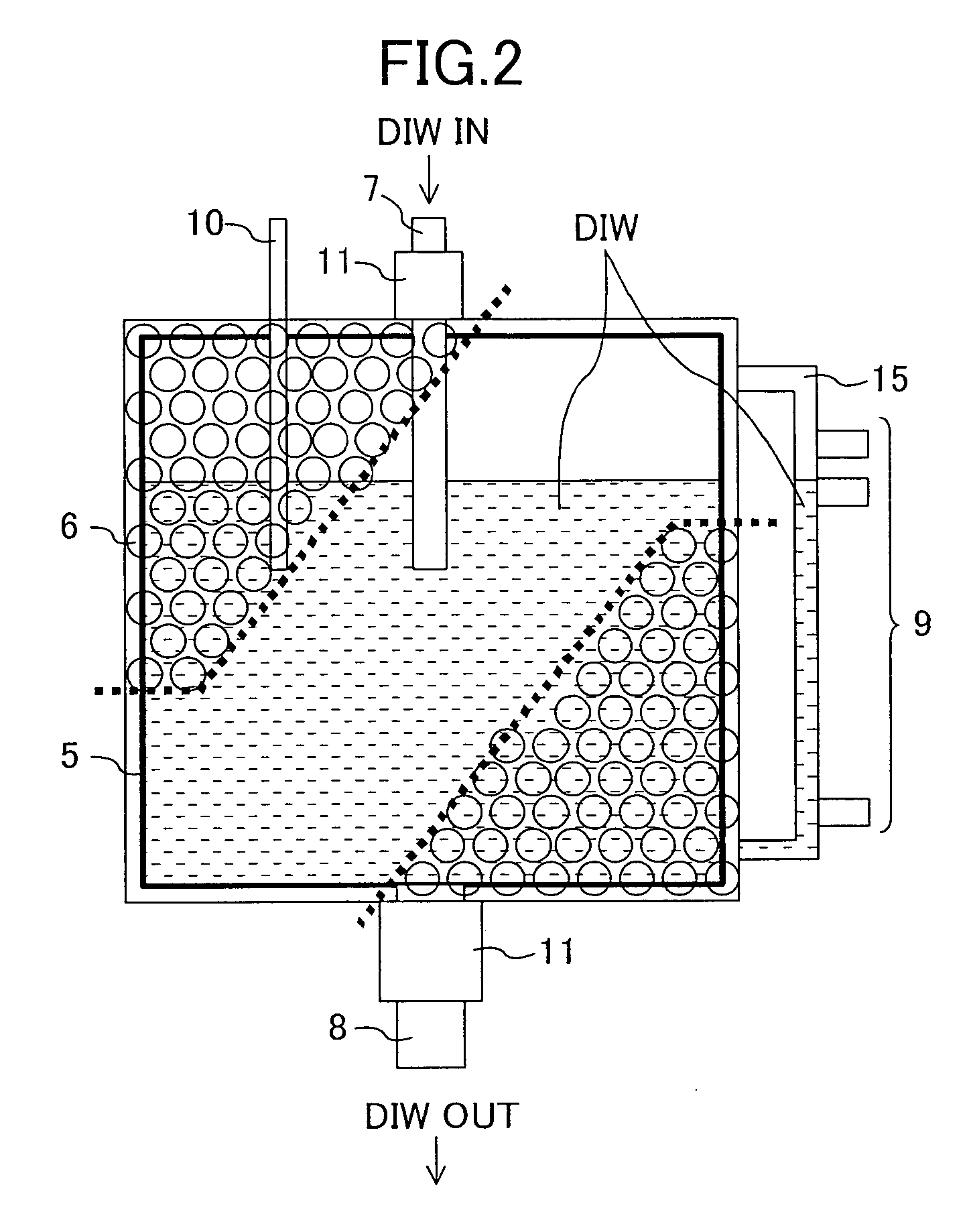
[0063] As shown in FIG. 1, a hot water production apparatus (liquid heating apparatus) of this embodiment comprises a pure water tank (reservoir) 5 for storing pure water (liquid), a supply pipe (supply passage) 7 for supplying pure water to the pure water tank 5, a drain 8 for draining pure water, a power supply 3, a microwave oscillator 1 connected through a cable to the power supply 3 and having a magnetron 2 that generates microwaves, a waveguide 4 that transmits the microwaves generated from the microwave oscillator 1 to the pure water tank 5 and irradiates the pure water tank 5 with microwaves, a microwave blocking plate (microwave blocker) 6 surrounding the entire surfaces of th...

embodiment 2

[0086]FIG. 9 is a schematic view showing an example of a cleaning apparatus and a hot water production apparatus according to a second embodiment of the present invention.

[0087] The hot water production apparatus shown in FIG. 9 is identical with the hot water production apparatus of the first embodiment shown in FIG. 1 but is characterized in that a microwave oscillator 1, a power supply 3 and a part of a waveguide 4 are placed outside the cleaning apparatus for cleaning semiconductor devices.

[0088] A hot water production apparatus of this embodiment comprises a pure water tank 5, a power supply 3, the microwave oscillator 1 connected through a cable to the power supply 3 and having a magnetron 2 that generates microwaves, the waveguide 4 that transmits microwaves generated from the microwave oscillator 1 to the pure water tank 5 and irradiates the pure water tank 5 with microwaves, and a microwave blocking plate 6 surrounding the entire surfaces of the pure water tank 5 to preve...

embodiment 3

[0092]FIG. 10 is a schematic view showing an example of a hot water production apparatus according to a third embodiment of the present invention.

[0093] A hot water production apparatus of this embodiment comprises a first pure water tank 5a, a second pure water tank 5b, a power supply 3, a microwave oscillator 1 connected through a cable to the power supply 3 and having a magnetron 2 that generates microwaves, a waveguide 4 that transmits microwaves generated from the microwave oscillator 1 to the first and second pure water tanks 5a and 5b and irradiates the first and second pure water tanks 5a and 5b with microwaves, a reflector (microwave reflector element) 22 disposed at a branch point of the waveguide 4 and made of a material that reflects microwaves, and a microwave blocking plate 6 surrounding the entire surfaces of the first and second pure water tanks 5a and 5b to prevent the leakage of microwaves. The hot water production apparatus of this embodiment is characterized by ...


PUM


Abstract

Microwaves are applied to pure water stored in a pure water tank past at least one of the top section of the sealed pure water tank, the side sections thereof and the bottom section thereof, thereby heating the pure water in a non-contact manner.

Description

CROSS-REFERENCE TO RELATED APPLICATIONS [0001] This application claims priority under 35 U.S.C. §119 on Patent Application No. 2004-229534 filed in Japan on Aug. 5, 2004, the entire contents of which are hereby incorporated by reference. The entire contents of Patent Application No. 2005-77350 filed in Japan on Mar. 17, 2005 are also incorporated by reference. BACKGROUND OF THE INVENTION [0002] (1) Field of the Invention [0003] The present invention relates to a liquid heating apparatus for providing a heated cleaning solution, a cleaning apparatus for cleaning objects, such as semiconductor substrates, using the heated cleaning solution, and a cleaning method using the same. [0004] (2) Description of Related Art [0005] In a semiconductor device fabrication process, yield reduction due to particles and metal impurities both deposited on semiconductor substrates has conventionally been a large problem. Therefore, the step of cleaning semiconductor substrates using a cleaning solution...

Claims


Application Information

Patent Timeline
Patent Type & Authority Applications(United States)
IPC IPC(8): H05B6/80
CPCH05B6/802H01L21/304
Inventor MIYOSHI, YUICHISUGANO, KOUSATOH, YASUO
Owner PANASONIC CORP
Why Eureka
Try Eureka