Rotor for rotating electric machine

a technology of rotating electric machines and rotating plates, which is applied in the direction of magnetic circuit rotating parts, magnetic circuit shapes/forms/construction, magnetic bodies, etc., can solve problems such as reliability degradation, and achieve the effects of reducing peak pressure, reducing mean pressure, and reducing peak pressur

Inactive Publication Date: 2006-02-09
HITACHI LTD
View PDF0 Cites 12 Cited by
  • Summary
  • Abstract
  • Description
  • Claims
  • Application Information

AI Technical Summary

Benefits of technology

[0006] Rounding or chamfering the edges of the cooling groove 10 is an effective means for achieving the object. Although the greater the radius of the rounded edges or the chamfer of the chambered edges, the greater the effect of rounding or chamfering on reducing the peak pressure, the great radius or chamfer increases the mean pressure. FIG. 8 shows the variation of the peak pressure and the mean pressure with the radius of a rounded edge. As shown in FIG. 8, the difference between the mean bearing pressure, i.e., (Load produced by centrifugal force)/(Area of contact surface), indicated by a dotted line and the peak pressure indicated by a continuous line is large when the radius R of rounded edge is below 0.1 mm, and the value of the mean pressure increases with the increase of the radius R beyond 2.0 mm. Although FIG. 8

Problems solved by technology

Then the turn insulation 13 is damaged due to the peak pressure induced a

Method used


Image

  • Rotor for rotating electric machine
  • Rotor for rotating electric machine
  • Rotor for rotating electric machine

Examples


Embodiment Construction

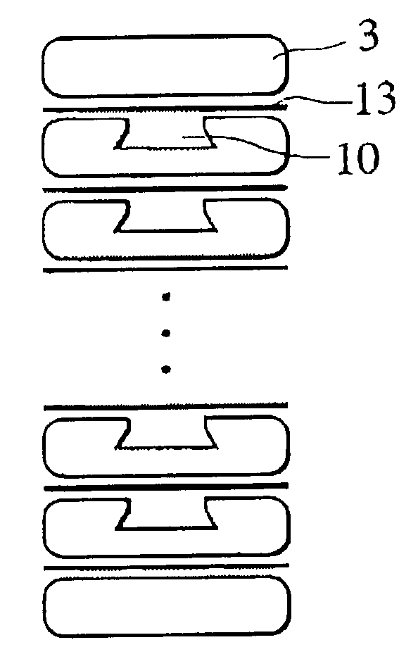
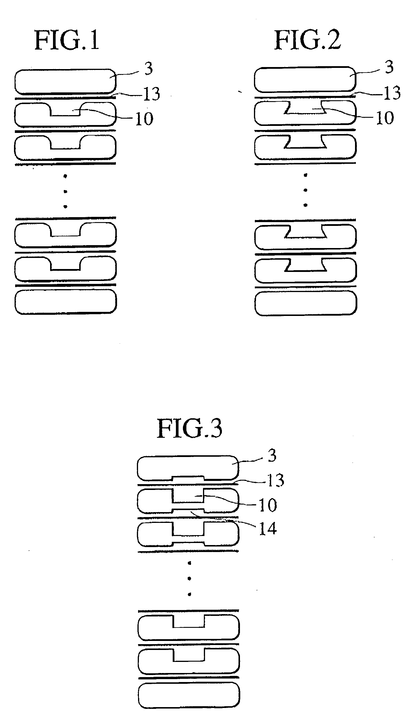
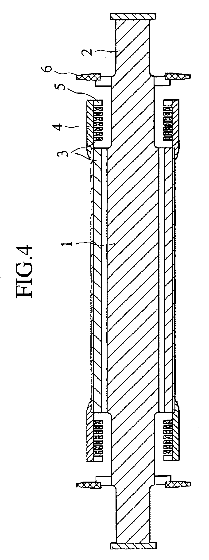
[0018]FIG. 4 is a schematic longitudinal sectional view of a rotor for a rotating electric machine. The rotor has a rotor core 1, and a rotor shaft 2 coaxial with the rotor core 1 and longitudinally projecting from the opposite ends of the rotor core 1. The rotor shaft 2 of the rotor is supported stably for rotation in bearings. As shown in FIG. 5, a body part of the rotor core 1 is provided with slots 7. A plurality of rotor conductors 3 are stacked in each slot 7. A field current flows through the rotor conductors 3. Cylindrical retaining rings 4 are mounted on opposite end parts of the rotor core 1 and are pressed against the opposite ends of the rotor conductors 3, respectively, to hold the opposite ends of the rotor conductors 3 in place against centrifugal force that acts on the opposite ends of the rotor conductors 3. Centering rings 5 are fitted in the retaining rings 4, respectively. Fans 6 for pressurizing a cooling medium are mounted on the opposite end parts of the rotor...


PUM

PropertyMeasurementUnit
Lengthaaaaaaaaaa
Lengthaaaaaaaaaa
Radiusaaaaaaaaaa

Abstract

A rotor for a rotating electric machine comprises a rotor core, and a plurality of rotor conductors wound on the rotor core. At least one of the rotor conductors is provided with a cooling groove, and edges of at least one of the cooling grooves are rounded by a radius process to reduce peak stresses that may be induced around the edges of the cooling groove.

Description

BACKGROUND OF THE INVENTION [0001] The present invention relates to a rotor for a rotating electric machine, and a rotating electric machine. [0002]FIG. 6 is a fragmentary sectional view of rotor conductors 3 stacked in an end part of a rotor for a rotating electric machine. Turn insulations 13 are held between the adjacent turns of the stacked rotor conductors 3 to isolate the turns of the stacked rotor conductors 3 electrically from each other. Techniques relating to turn insulation are disclosed in Japanese Patent Laid-open No. 5-300683. [0003] When a cooling groove 10 is formed in a rotor conductor 3 to improve the cooling characteristic of the rotor conductor 3, a mean pressure that acts on the rotor conductor 3 is greater than a mean pressure that acts on the rotor conductor 3 before the cooling groove 10 is formed therein, and peak pressure are induced around the edges of the cooling groove 10 as typically represented by a stress distribution curve shown in FIG. 7. In a large...

Claims


Application Information

Patent Timeline
IPC IPC(8): H02K9/00H02K1/22H01F7/06H02K3/24
CPCY10T29/49073H02K3/24
Inventor KOMURA, AKIYOSHIIDE, KAZUMASAWATANABE, TAKASHIHATTORI, KENICHITSUNODA, TOMOYAODAJIMA, SHINYAAOYAMA, HIROSHI
Owner HITACHI LTD
Why Eureka
Try Eureka