Conduit connection assembly, a turbine inlet conduit, a turbo charger and a vehicle

a technology for connecting assemblies and turbines, which is applied in the direction of liquid fuel engines, combustion air/fuel air treatment, machines/engines, etc. it can solve the problems of pulsation damping devices, particularly pronounced problems, and complicated pulsation damping devices, so as to reduce the complexity and cost of the conduit connection assembly, and simplify the sealing element. the effect of cost reduction

Active Publication Date: 2018-10-18
VOLVO LASTVAGNAR AB
View PDF0 Cites 3 Cited by
  • Summary
  • Abstract
  • Description
  • Claims
  • Application Information

AI Technical Summary

Benefits of technology

[0003]US2013111901A1 describes for a turbo charged engine a pulsation absorption device with a resonator, a diaphragm, or a bladder, in order to avoid compressor surge which according to US2013111901A1 might be caused by pulsations in the exhaust flow. ER2879689A1 describes a damping chamber on a compressor side of a turbo charger for reducing pressure pulses from the compressor. However, such known pulsation damping devices are complex and therefore add cost to the vehicle. Also, said FR2879689A1 does not provide any relief of pressure pulses on the turbine side of the turbo charger. Where a device according to said US2013111901A1 is placed on the turbine side, upstream of a turbo charger, the reduced peak pressure can reduce the performance of the turbo charger.
[0033]The pressure in the first conducting volume being, during operation of the internal combustion engine, higher than the pressure in the second conducting volume, might be due to the first fluid conducting volume being, in the assembled state of the assembly, partly formed by a turbine inlet conduit of a turbo charger for an internal combustion engine, and the second fluid conducting volume being at least partly formed by a turbine outlet conduit of the turbo charger. Thereby, due to the draining connection, the sealing abutment of the conduit connection assembly will be exposed to substantially the same pressure as that in the second fluid conducting volume. This will considerably reduce the high pressure exposure to the sealing abutment. This lower pressure will also contribute to reducing or eliminating the exposure of the sealing abutment to pressure pulses in the first fluid conducting volume. At the same time, the high pressure and the pressure pulses may be retained in the first fluid conducting volume, thereby retaining a high turbo charger efficiency.

Problems solved by technology

Engine operation may cause pulsations in such conduits, which may have detrimental effects to devices in the conduits or the operation of the engine.
This problem is particularly pronounced where the engine is provided with a turbo charger, and the conduits are located where high pressures occur during turbo charger operation.
However, such known pulsation damping devices are complex and therefore add cost to the vehicle.
Also, said FR2879689A1 does not provide any relief of pressure pulses on the turbine side of the turbo charger.
Where a device according to said US2013111901A1 is placed on the turbine side, upstream of a turbo charger, the reduced peak pressure can reduce the performance of the turbo charger.

Method used


Image

  • Conduit connection assembly, a turbine inlet conduit, a turbo charger and a vehicle
  • Conduit connection assembly, a turbine inlet conduit, a turbo charger and a vehicle
  • Conduit connection assembly, a turbine inlet conduit, a turbo charger and a vehicle

Examples


Embodiment Construction

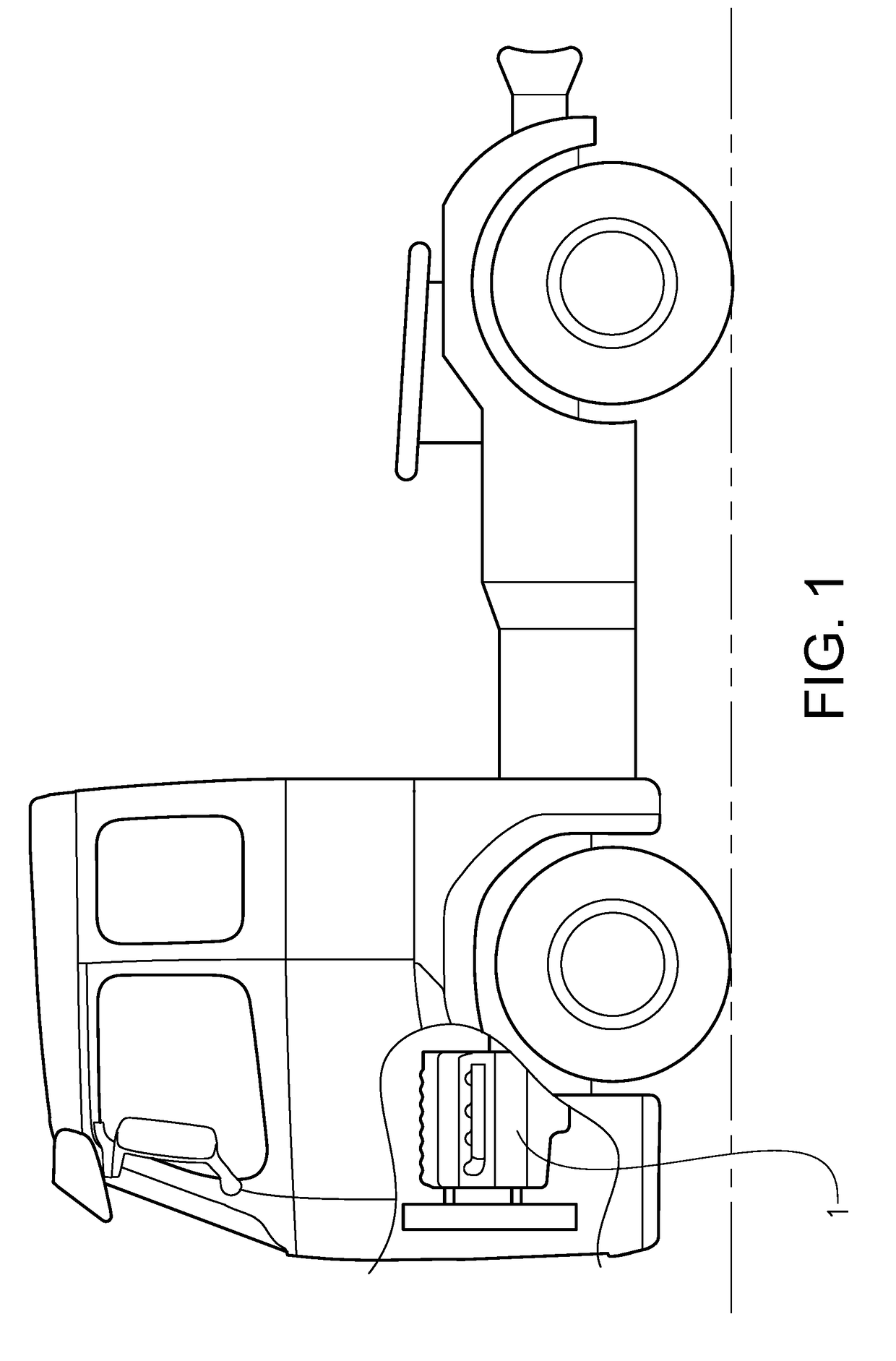
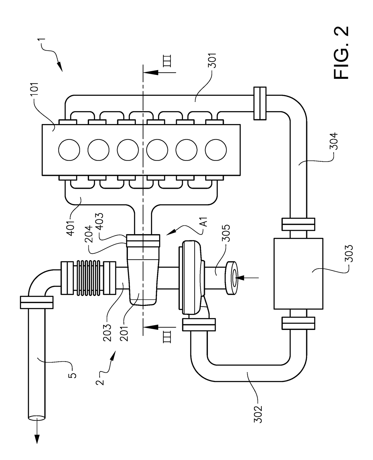
[0054]FIG. 1 shows a vehicle in the form of a truck with an internal combustion engine 1 comprising an engine block 101 with a number of cylinders, in this example six. As can be seen in FIG. 2, the engine 1 is provided with a turbo charger 2 adapted to provide pressurised inlet, air to an inlet manifold 301 via a first charged air conduit 302, an intercooler 303 and a second charged air conduit 304. An air admission conduit 305 is adapted to guide air to the turbo charger 2. The turbo charger 2 is adapted to be driven with a flow of exhaust gases provided via an exhaust manifold 401 of the engine. Downstream of the turbo charger 2 an exhaust conduit 5 is provided.

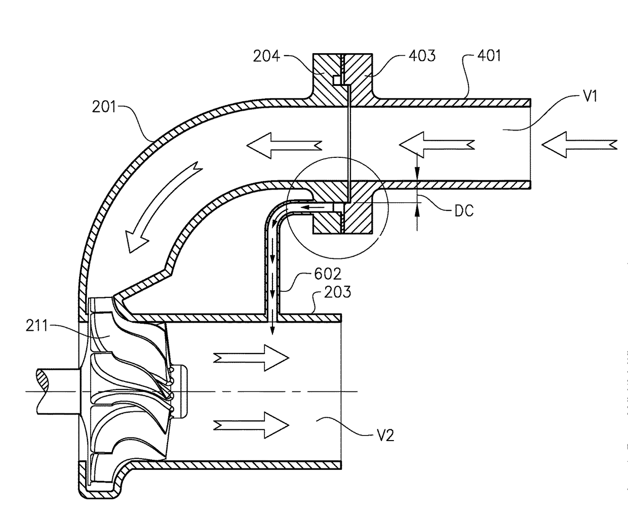
[0055]The turbo charger comprises a turbine inlet conduit 201. The turbine inlet conduit 201 and the exhaust manifold 401 form parts of what is herein referred to as a conduit connection assembly A1, wherein the turbine inlet conduit 201 forms what is herein referred to as a first conduit part, and the exhaust manifold for...


PUM


Abstract

A conduit connection assembly including a first conduit part and a second conduit part, adapted to be assembled to form a conduit connection delimiting a first fluid conducting volume, wherein the conduit connection assembly presents a second fluid conducting volume, the first and second fluid conducting volumes being arranged to communicate with each other via a pressure change inducing device so as to form a common fluid guide, whereby during use of the conduit connection assembly the pressure in the first conducting volume is higher than the pressure in the second conducting volume, in that a cavity is formed between the first and second conduit parts at a distance from the first conducting volume, and a draining connection is adapted to provide a communication between the cavity and the second fluid conducting volume.

Description

BACKGROUND AND SUMMARY[0001]The invention relates to a conduit connection assembly, a turbo charger for an internal combustion engine, an internal combustion engine and a vehicle.[0002]In typical vehicles, conduits provide air to an internal combustion engine of the vehicle, and guide exhaust gases from the engine. Engine operation may cause pulsations in such conduits, which may have detrimental effects to devices in the conduits or the operation of the engine. This problem is particularly pronounced where the engine is provided with a turbo charger, and the conduits are located where high pressures occur during turbo charger operation.[0003]US2013111901A1 describes for a turbo charged engine a pulsation absorption device with a resonator, a diaphragm, or a bladder, in order to avoid compressor surge which according to US2013111901A1 might be caused by pulsations in the exhaust flow. ER2879689A1 describes a damping chamber on a compressor side of a turbo charger for reducing pressu...

Claims


Application Information

Patent Timeline
Patent Type & Authority Applications(United States)
IPC IPC(8): F16L55/052F01N13/18F01D9/06F02B33/44F02B29/04F02M35/104F02B41/10F02B37/02F16L39/00F16L23/00
CPCF16L55/052F01N13/1827F01D9/06F02B33/44F02B29/04F02M35/104F02B41/10F02B37/02F16L39/00F16L23/00F05D2260/6022F05D2220/40F05D2260/606F01N13/1805F01N13/1855F02B39/16F01N1/026F04D29/665F16L55/04F01N2260/16F04D29/083F02C7/28F01D9/02Y02T10/12
Inventor ANDERSSON, PETERRAHM, FREDRIK
Owner VOLVO LASTVAGNAR AB
Why Eureka
Try Eureka