Hydraulic drive device

A driving device and hydraulic technology, which is applied in the direction of power device, fluid pressure actuating device, transmission device control, etc., can solve problems such as the limit of large diameter, damage to the cooling effect of hydraulic motor, etc., and achieve the effect of reducing peak pressure

Inactive Publication Date: 2016-03-02
KOMATSU LTD
View PDF9 Cites 3 Cited by
  • Summary
  • Abstract
  • Description
  • Claims
  • Application Information

AI Technical Summary

Problems solved by technology

However, when the amount of oil to be flushed is reduced, the cooling effect of the hydraulic motor may be impaired
In addition, even if the method of reducing the pressure loss of the tank oil circuit is adopted, due to the limitation of the projected area of ​​the work vehicle, there is a limit to increasing the pipe size.

Method used


Image

  • Hydraulic drive device
  • Hydraulic drive device
  • Hydraulic drive device

Examples


Embodiment approach 1

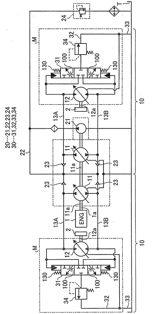
[0031] figure 1 It is a hydraulic circuit diagram showing the hydraulic drive device according to Embodiment 1 of the present invention. The hydraulic drive device illustrated here is a hydraulic drive device for driving a work vehicle used as a construction machine such as a wheel loader and a forklift, and includes an independent hydraulic transmission unit 10 between the engine 1 and the left and right drive wheels 2 . Since the hydraulic transmission unit 10 provided for each driving wheel 2 has the same structure, only one of them will be described below, and the other will be assigned the same reference numerals and its description will be omitted.

[0032] The hydraulic transmission unit 10 is also called a so-called HST (Hydro-Static Transmission), and is configured to include a hydraulic pump 11 driven by the engine 1, a hydraulic motor 12 for traveling driven by oil supplied from the hydraulic pump 11, and a hydraulic motor 12 for constituting A pair of main oil p...

Embodiment approach 2

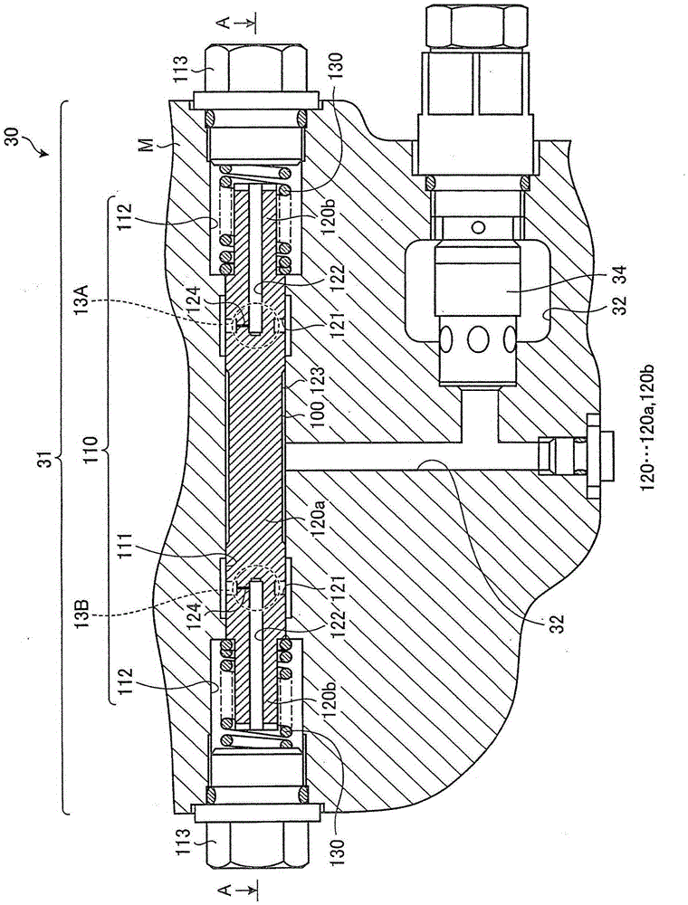
[0051] Figure 5-1 as well as Figure 5-2 Main parts of the hydraulic drive device according to Embodiment 2 of the present invention are shown. Also in this second embodiment, the low-pressure selector valve 31 is constituted by arranging the spool valve 120 in the spool valve hole 110 formed in the motor housing M similarly to the first embodiment. structure is different. That is, in Embodiment 2, the throttle portion 100 of Embodiment 1 is not formed between the slide hole portion 111 of the spool valve hole 110 and the gap forming portion 123 of the spool valve 120 , and therefore the throttle portion 100 of Embodiment 1 is formed by placing the spool valve base portion 120a outside When the diameter is D0, the outer diameter of the gap forming portion 123 is d0, and the throttle length is L0, it becomes 10.0<(δ^2)d0 / L0 (where, δ=(D0-d0) / 2), the gap forming part 123 is configured.

[0052] On the other hand, a throttle rod 210 is arranged on a straight line portion be...

Embodiment approach 3

[0057] Figure 6-1 as well as Figure 6-2 The main part of the hydraulic drive system of Embodiment 3 of this invention is shown. Also in this third embodiment, the low-pressure selector valve 31 is constituted by arranging the spool valve 120 in the spool valve hole 110 formed in the motor housing M similarly to the first embodiment. structure is different. That is, in Embodiment 3, the throttle portion 100 of Embodiment 1 is not formed between the slide hole portion 111 of the spool hole 110 and the gap forming portion 123 of the spool valve 120 , so that the spool base portion 120 a When the outer diameter is D0, the outer diameter of the gap forming part 123 is d0, and the throttle length is L0, 10.0<(δ^2)d0 / L0 (where δ=(D0-d0) / 2) The gap forming part 123 is configured.

[0058]On the other hand, in the case discharge oil passage 32 , the diameter of the straight portion with the oil-filled safety valve 34 is reduced to form a throttle portion 300 based on cylindrical...


PUM


Abstract

In order to suppress the occurrence of a peak pressure inside a motor case (M) without compromising the cooling effect of a hydraulic motor (12), a hydraulic drive device includes, the hydraulic motor (12) which is operated by an oil being circulated through a main oil path (13A) and a main oil path (13B) which are connected to the motor case (M), a low-pressure selection valve (31) which is operated depending on a differential pressure between the main oil path (13A) and the main oil path (13B) so as to discharge the oil in the main oil path (13B) into the motor case (M), and a tank oil path (33) connecting the inside of the motor case (M) to an oil tank (T), wherein a choke aperture (100) by annular gap flow is interposed in the low-pressure selection valve (31).

Description

technical field [0001] The present invention relates to a hydraulic drive device, particularly a hydraulic drive device suitable for driving a traveling hydraulic motor mounted on a work vehicle used as a construction machine. Background technique [0002] A work vehicle used as a construction machine such as a wheel loader or a forklift has a structure in which a hydraulic motor is operated by oil supplied from a hydraulic pump, and traveling wheels provided on an output shaft of the hydraulic motor are rotated to travel. In a hydraulic drive device suitable for such a work vehicle, the oil in the low-pressure oil circuit is discharged to the motor case of the hydraulic motor through the low-pressure selector valve, and then discharged (flushed) from the motor case to the oil tank through the tank oil circuit. On the one hand, a charge pump is used to supply the oil in the oil tank to the low-pressure oil circuit, and the hydraulic motor is cooled by leading the oil out of ...

Claims


Application Information

Patent Timeline
Patent Type & Authority Applications(China)
IPC IPC(8): F16H61/4104F03C1/26F04B23/04
CPCF03C1/26F16H61/4104F16H61/44E02F9/20E02F9/22B60K8/00B66F9/07572E02F9/2225E02F9/2289F15B11/08F15B13/0401F15B13/042F15B2013/008
Inventor 宫田拓也内藤忍
Owner KOMATSU LTD
Why Eureka
Try Eureka