Video monitoring system using daisy chain

Inactive Publication Date: 2006-02-09
ALOGICS
View PDF5 Cites 4 Cited by
  • Summary
  • Abstract
  • Description
  • Claims
  • Application Information

AI Technical Summary

Benefits of technology

[0007] Therefore, the present invention has been made in view of the above problems, and the present invention provides a video monitoring system using daisy chain, which can display more than four divided screens on one display screen with a simple configuration of the video monitoring system by bypassing video signals captured by a plurality of video cameras through many stages.
[0008] The present invention also provides a video monitoring system using daisy chain, which can display a plurality of channel video images on divided screens within one display screen by arbitrarily extending the number of divided screens with a single memory.
[0011] one or more slave video signal processors coupled by daisy chain for reducing the digital video data of each channel outputted from the A / D converters through a video source channel, collecting the digital video data of the video source channel outputted through a first bypass channel placed at a front stage of a slave video signal processor and the digital video data of the video source channel outputted through a second bypass channel placed at the front stage of the slave video signal processor, and outputting the collected video data to the second bypass channel;
[0014] The slave video signal processor reduces the digital video data of the video source channel corresponding to the video signals captured by each video camera and then outputs the reduced digital video data. The slave video signal processor bypasses the digital video data from another slave video signal processor placed at its front stage, thereby outputting the bypassed digital video data to another slave video signal processor placed at its rear stage. The master video signal processor may record the digital video data of the video source channel corresponding to the video signals captured by respective video cameras and the digital video data bypassed from the slave video signal processor placed at its front stage in the frame memory, thereby configuring multiple channel divided screens and then outputting the configured multiple channel divided screens. Therefore, the video monitoring system may display the multiple channel divided screens with a simple configuration of the system.

Problems solved by technology

There is a problem in that a configuration of the conventional video monitoring system is complicated to configure with more than the four divided screens, and costs for system construction are increased.

Method used


Image

  • Video monitoring system using daisy chain
  • Video monitoring system using daisy chain
  • Video monitoring system using daisy chain

Examples


Embodiment Construction

[0023] Now, exemplary embodiments of the present invention will be described in detail with reference to the annexed drawings. In the following description, a detailed description of known functions and configurations incorporated herein will be omitted when it may make the subject matter of the present invention rather unclear.

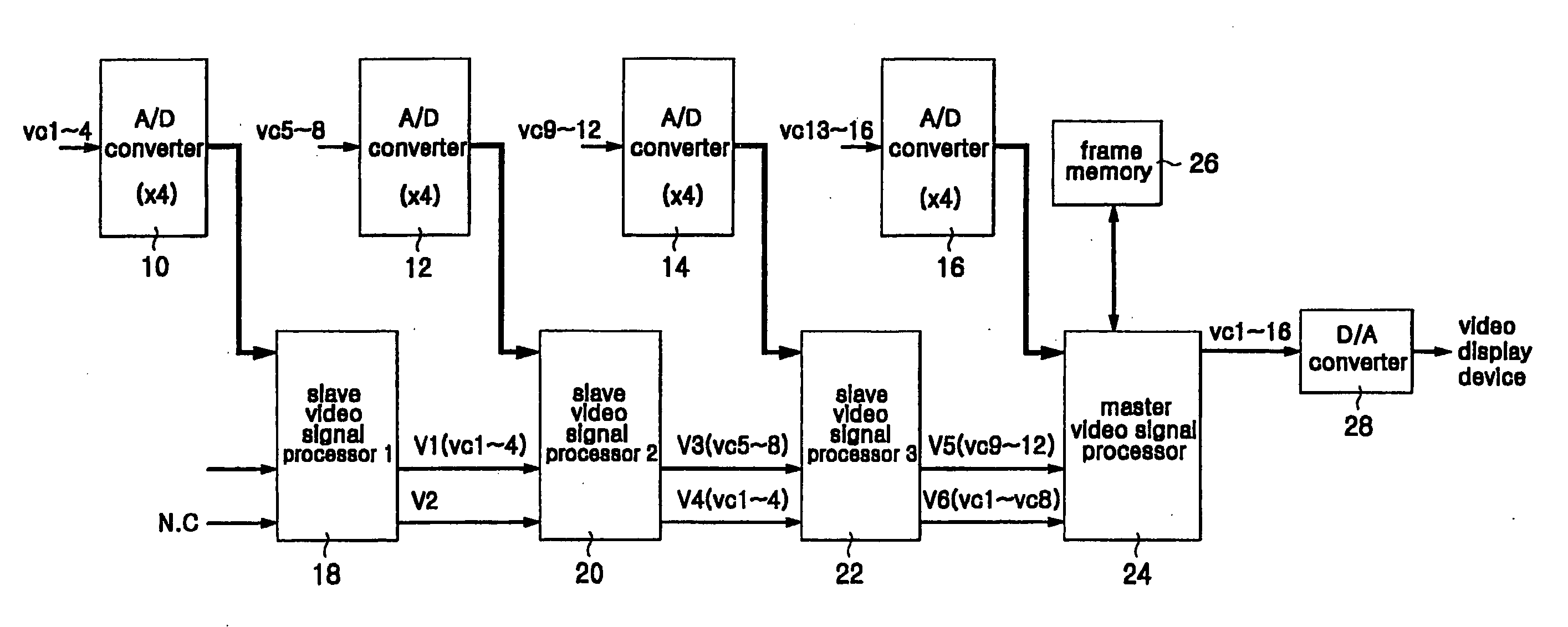
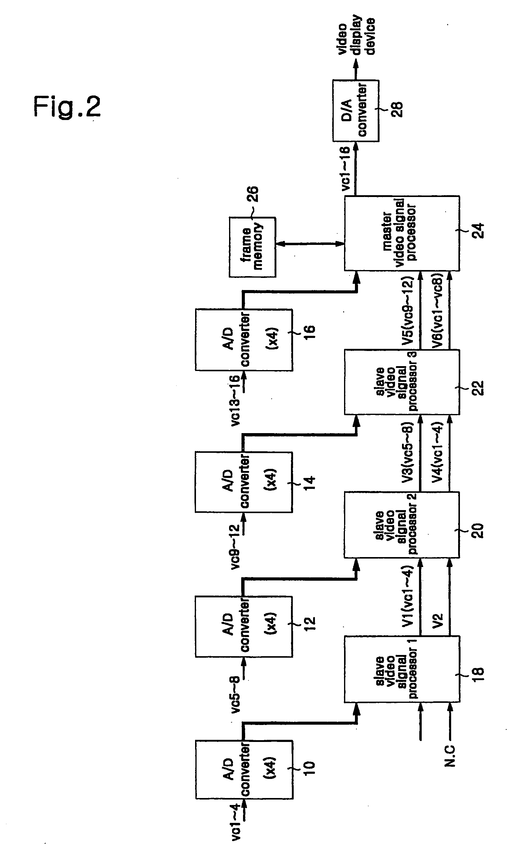
[0024]FIG. 2 is a view showing a configuration of a video monitoring system using daisy chain in accordance with a first embodiment of the present invention. In more detail, FIG. 2 is a view showing a configuration of a video monitoring system for displaying sixteen divided display screens on a video display device.

[0025] As shown in FIG. 2, the video monitoring system for displaying the sixteen divided display screens comprises three slave video signal processors 18, 20 and 22 and one master video signal processor 24. The slave video signal processors 18, 20 and 22 and master video signal processor 24 will be described below and can be composed of the same...


PUM


Abstract

A video monitoring system using daisy chain is disclosed. A video monitoring system uses daisy chain, which can display more than four divided screens on one display screen with a simple configuration of the video monitoring system by bypassing video signals captured by a plurality of video cameras through many stages.

Description

CROSS-REFERENCE TO RELATED APPLICATIONS [0001] The present application is a continuation-in-part of the earlier filed non-provisional application, having U.S. application Ser. No. 10 / 332,207, filed on Jan. 3, 2003, which is incorporated herein in its entirety.FIELD OF THE INVENTION [0002] The present invention relates to a video monitoring system, and more particularly to a video monitoring system using daisy chain. DESCRIPTION OF THE RELATED ART [0003] A conventional video monitoring system is installed in a general house, department store, bank, factory, exhibition hall, etc. to monitor visitors and prevent a burglary. The conventional video monitoring system comprises a plurality of video cameras for capturing video signals corresponding to objects of monitored areas, a signal processor for processing video signals captured by video cameras, and a video display device for displaying video images corresponding to the processed video signals on one display screen having divided dis...

Claims


Application Information

Patent Timeline
IPC IPC(8): H04N7/18H04N5/265H04N5/262
CPCG08B13/19656H04N7/181H04N5/2624G08B13/19693
Inventor KIM, HAK-SUNG
Owner ALOGICS
Why Eureka
Try Eureka