Head arm assembly, head stack assembly and disk drive unit using the same

a technology of head stack and assembly, which is applied in the direction of magnetic recording, data recording, instruments, etc., can solve the problems of increasing the cost of manufacturing disk drive units, affecting the shock performance of traditional haa, and consuming a lot of time in the assembly process of disk drive units, so as to achieve good shock performance and small mass

Inactive Publication Date: 2006-02-09
SAE MAGNETICS (HK) LTD
View PDF14 Cites 9 Cited by
  • Summary
  • Abstract
  • Description
  • Claims
  • Application Information

AI Technical Summary

Benefits of technology

[0006] A main feature of the present invention is to provide a HAA with small mass and a good shock performance, and a disk dirve unit having such a HAA.
[0007] Another feature of the present invention is to provide a HSA with small mass and a good shock performance, and a disk dirve unit having such a HSA.
[0011] Compared with the prior art, firstly, because the HAA (HSA, disk drive) of the present invention has no additional flexure so as to omit the manufacturing process of the flexure and the assembly process with the load beam. Thus, it makes manufacturing HAA (HSA, disk drive) much easily and accordingly lows down the manufacturing cost thereof. In addition, omitting the additional flexure can also reduce the whole height and weight of the HAA (HSA, disk drive), that is, reducing the whole mass of the HAA (HSA, disk drive). This is because the related art must superpose the flexure with the load beam in a certain area for assembling them together, and accordingly the superposing portions of the flexure and the load beam will increase the whole height and weight of the HAA (HSA, disk drive). At the same time, reducing the weight of HAA (HSA, disk drive) will decrease its inertia and then attain a good shock performance. Furthermore, a stiffener, i.e. rails, is provided on the hinge portion so that the load beam is stiff enough to urge the slider to maintain a desired position relative to disk surface.

Problems solved by technology

However, the traditional HAA has not a good shock performance because of its rather large and complicated structure.
In addition, the complicated structure of the HAA also makes the manufacturing and assembly process of the disk drive unit rather time-consuming, and accordingly increases the cost of manufacturing disk drive unit.

Method used


Image

  • Head arm assembly, head stack assembly and disk drive unit using the same
  • Head arm assembly, head stack assembly and disk drive unit using the same
  • Head arm assembly, head stack assembly and disk drive unit using the same

Examples


first embodiment

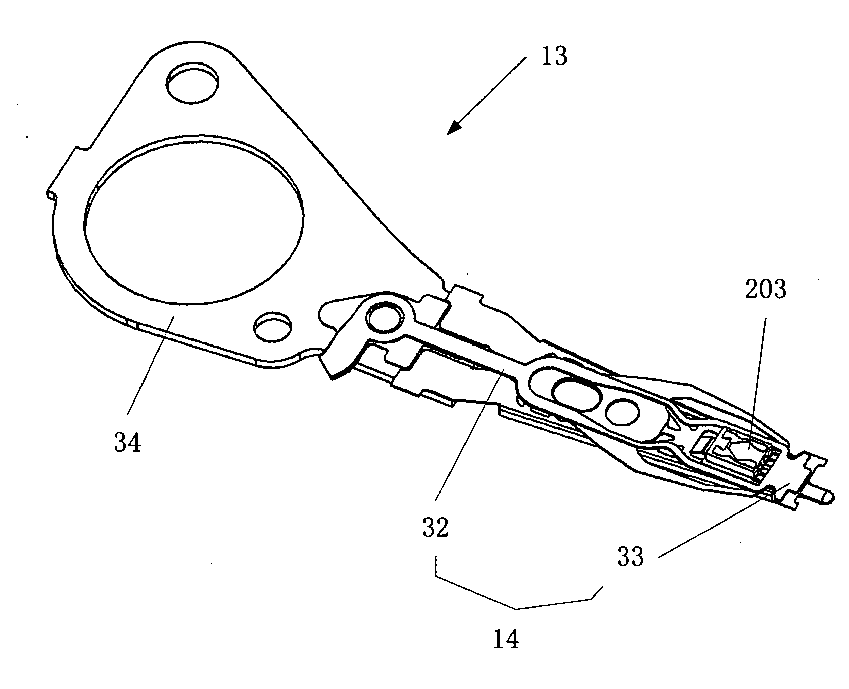
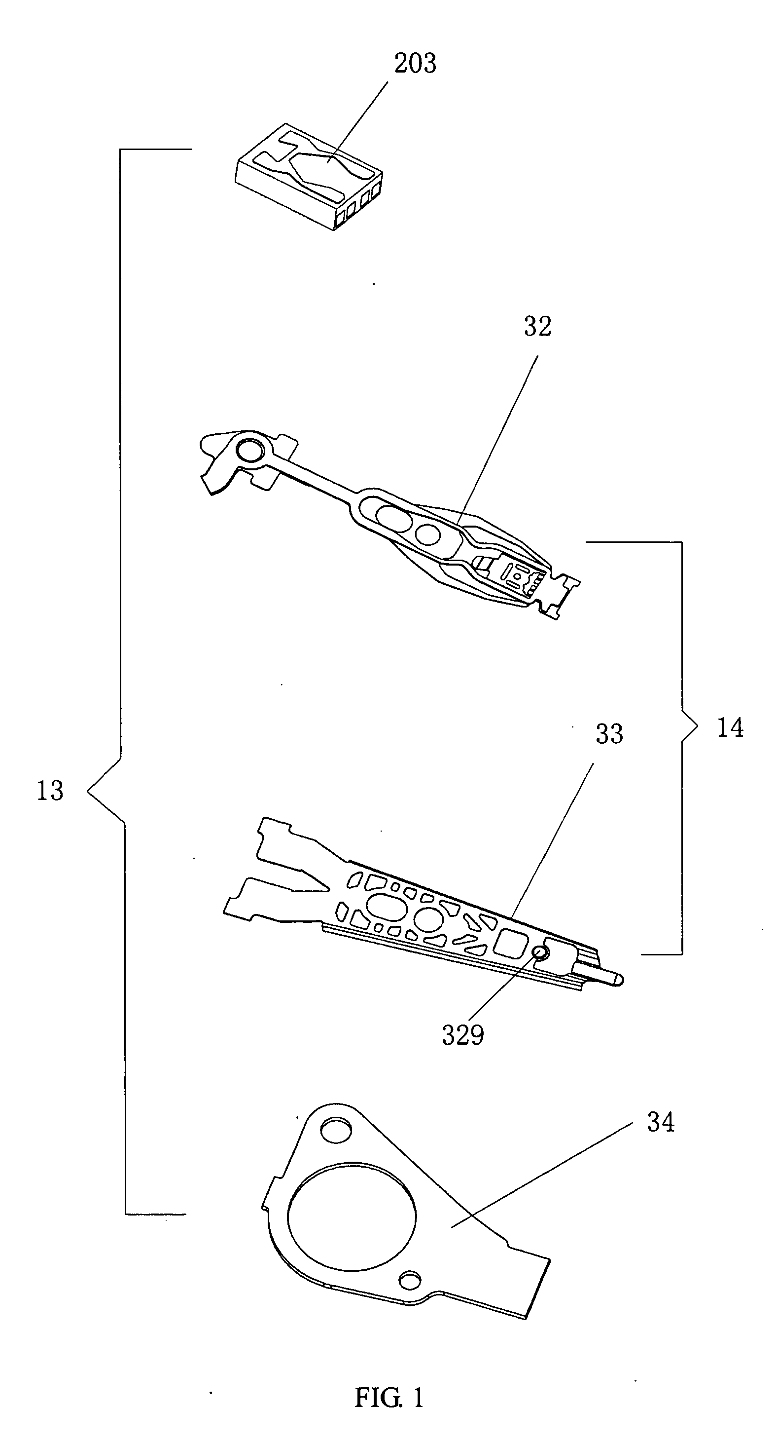
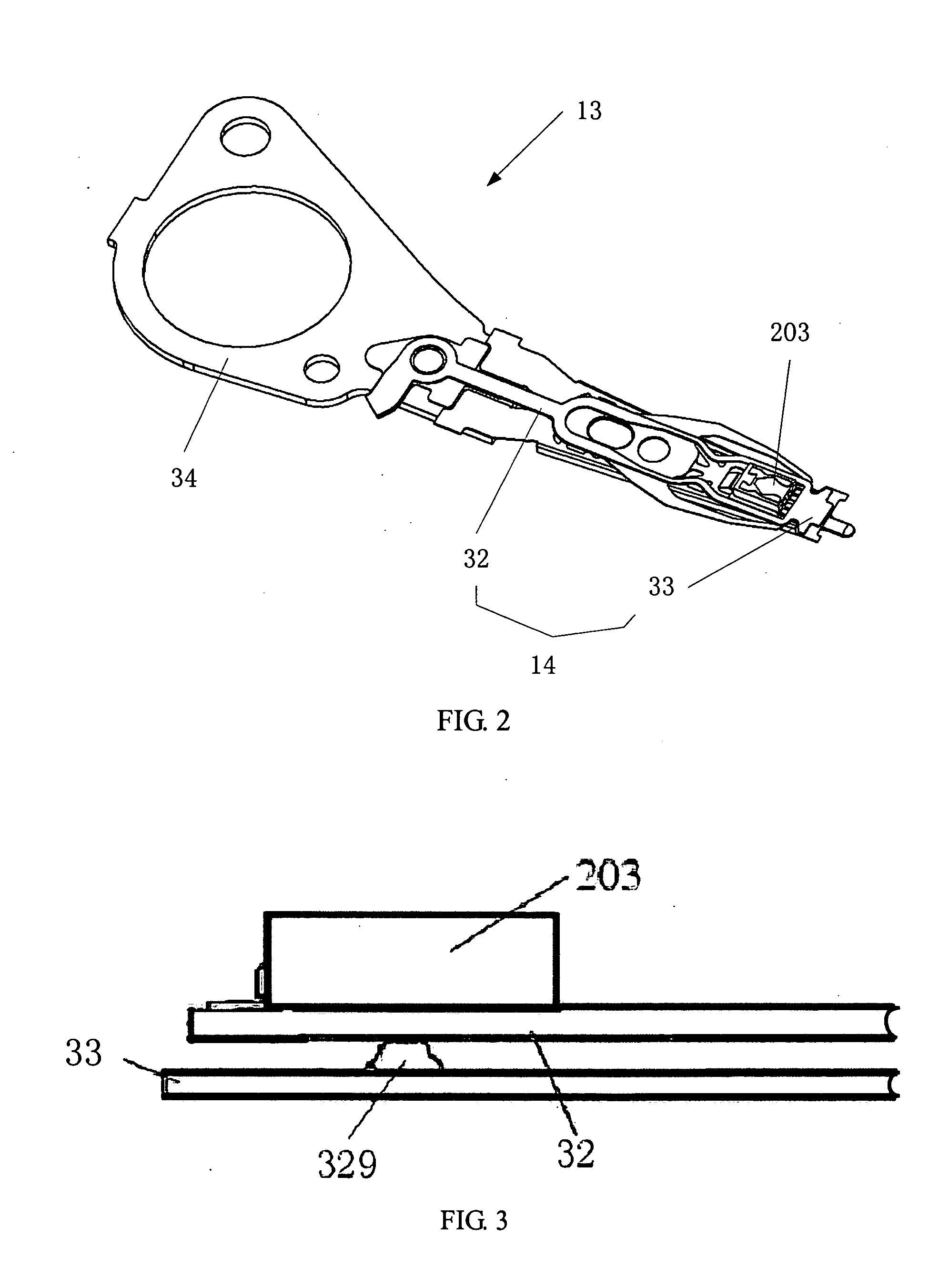
[0026] According to the present invention, referring to FIG. 4, a HAA 13′ comprises a slider 203′, a drive arm 34′ and a load beam 33′ to load the slider 203′. The load beam 33′ has an integral structure and electric traces 309 formed thereon.

[0027] In the present invention, the load beam 33′ is an interconnecting piece where the electric traces 309 is integrated therewith and provide conductivity between a PCBA (not shown) and the slider 203′. In the invention, the load beam 33′ can be made by a laminate, such as trace suspension assembly (TSA), circuit integrated suspension (CIS), or flex suspension assembly (FSA). After the load beam 33′ are formed, it will be coupled to the drive arm 34′ by welding or other traditional method.

[0028] Referring to FIG. 4, the load beam 33′ comprises a hinge portion 391, a slider mounting portion 392 and a connecting portion 399 to connect the hinge portion 391 and the slider mounting portion 392. In the present invention, when a force is applied ...

second embodiment

[0031] According to the present invention, referring to FIG. 9, a HAA 13″ comprises a load beam 33″, a slider 203′ mounted thereon, and a drive arm 34′ coupled with the load beam 33″. The load beam 33″ comprises a hinge portion 391′, a slider mounting portion 392′ and a connecting portion 399′ to connect the hinge portion 391′ and the slider mounting portion 392′. A lift tab 332′ extends from the connecting portion 399′ to front end of the slider mounting portion 392′. Two rails 80 are formed from two side portions of the connecting portion 399′ to two side portions of the slider mounting portion 392′ in a longitudinal direction of the HAA 13″. In the embodiment, no other change except the above-mentioned is happened on the structure of the HAA 13″ comparing with the HAA 13′. Therefore, a detailed description thereof is omitted herefrom.

third embodiment

[0032] According to the present invention, referring to FIG. 9A, a HAA 3 comprises a load beam 63, a slider 203′ mounted thereon, and a drive arm 34′ coupled with the load beam 63. In an embodiment, referring to FIGS. 9B-9C, the load beam 63 is made of FSA, which comprises a stainless steel substrate 67 and a flex on suspension (FOS) portion 62 on the stainless steel substrate 67. The FOS portion 62 is attached to the stainless steel substrate 67 with adhesive or other traditional method. As an embodiment, the FOS portion 62 is mainly made of polyimide (PI), which is formed a PI layer (insulation layer); electric traces 309 are built on the PI layer. In the embodiment, the load beam 63 comprises a hinge portion 75, a slider mounting portion 73 and a connecting portion 72 to connect the hinge portion 75 and the slider mounting portion 73. A lift tab 78 extends from the connecting portion 72 to front end of the slider mounting portion 73. Also, two rails 66 are formed from two side po...


PUM

PropertyMeasurementUnit
flexibleaaaaaaaaaa
bendingaaaaaaaaaa
massaaaaaaaaaa

Abstract

A head arm assembly comprises a slider, a drive arm, a trace; and a load beam having a hinge portion and a slider mounting portion; wherein the slider mounting portion has a slider support portion to support flying attitude of the slider. The slider support portion has a slider mounting frame with a flexible lifter to maintain the slider position in a predetermined position. In the present invention, the flexible lifter has a spring structure. The load beam may further comprise a stiffener formed in a longitudinal direction of the head arm assembly. The invention also discloses a head stack assembly and a disk drive using the head arm assembly.

Description

FIELD OF THE INVENTION [0001] The present invention relates to head arm assemblies, head stack assemblies and disk drive units. BACKGROUND OF THE INVENTION [0002] Disk drives are information storage devices that use magnetic media to store data. A typical disk drive unit in related art comprises a magnetic disk and a head stack assembly (abbreviated as “HSA”, HSA with only one HGA is referred as “HAA” (head arm assembly)). The magnetic disk is mounted on a spindle motor which causes the magnetic disk to spin and a voice-coil motor (VCM) is provided for controlling the motion of the HSA and thus controlling slider (not labeled) on the HSA to move from track to track across the surface of the magnetic disk to read data from or write data to the magnetic disk. [0003] Referring to FIGS. 1 and 2, a traditional HAA 13 comprises a drive arm 34, a suspension 14 coupled with the drive arm 34, and a slider 203 mounted on the suspension 14 (the suspension 14 with the slider 203 is referred as ...

Claims


Application Information

Patent Timeline
Patent Type & Authority Applications(United States)
IPC IPC(8): G11B5/48
CPCG11B5/4833G11B5/4826
Inventor ZHOU, HAIMINGYANG, HUAIJIANG, HAIHUAHE, FEIZHANG, JIANBIN
Owner SAE MAGNETICS (HK) LTD
Why Eureka
Try Eureka