Catheter shaft tubes and methods of making

a technology of catheter shaft and tube body, applied in the field of catheter shaft tubes, can solve the problems of limited selection of polymer materials available for all but the innermost layer, manufacturing difficulties,

Inactive Publication Date: 2006-02-09
CODMAN & SHURTLEFF INC
View PDF39 Cites 158 Cited by
  • Summary
  • Abstract
  • Description
  • Claims
  • Application Information

AI Technical Summary

Problems solved by technology

However, if an outer layer is applied to an existing inner layer, and the outer layer melting temperature is greater than that of the inner layer, then the excessive temperature may cause manufacturi...

Method used


Image

  • Catheter shaft tubes and methods of making
  • Catheter shaft tubes and methods of making
  • Catheter shaft tubes and methods of making

Examples


Embodiment Construction

[0030] The following description of the preferred embodiments of the present invention is merely illustrative in nature, and as such it does not limit in any way the present invention, its application, or uses. Numerous modifications may be made by those skilled in the art without departing from the true spirit and scope of the invention.

[0031] Catheters:

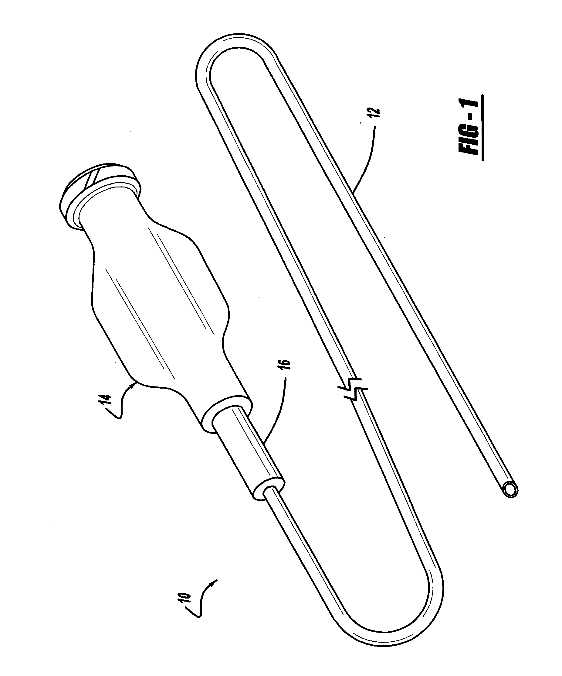
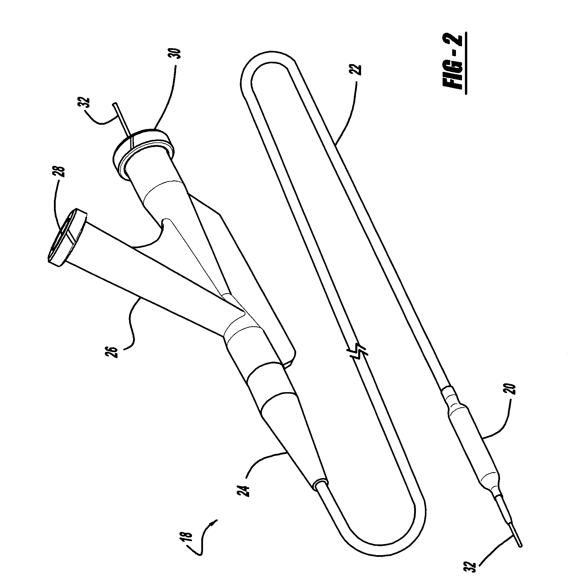
[0032] Generally, the present inventions have to do with catheters, and tubes for use in catheter shafts, as well as methods of making such tubes and catheters. Referring to the drawings, some examples of catheters are shown in FIGS. 1 and 2. Of course, they are only two possible examples of the various types of catheters with shafts having tubes that may be made according to the principles of the present invention.

[0033] The catheter 10 of FIG. 1 has a relatively long and flexible tubular shaft 12, a hub 14, and a flexible strain relief 16. The shaft 12 extends from a distal end to a proximal end, where the hub 14 and strain rel...


PUM

PropertyMeasurementUnit
Densityaaaaaaaaaa
Flexibilityaaaaaaaaaa
Distanceaaaaaaaaaa

Abstract

Catheter shaft tubes and methods for making them are described, in which a tubular member has two or more polymer layers, with some kind of reinforcement between at least two of the polymer layers. An inner polymer layer has a lower melting temperature than an outer polymer layer.

Description

CROSS-REFERENCE TO RELATED APPLICATION [0001] The present application is a continuation-in-part of Ser. No. 10 / 879,861, entitled “Balloon Catheter Shaft Design,” filed Jun. 29, 2004.BACKGROUND AND SUMMARY OF THE INVENTION [0002] 1. Technical Background [0003] The present invention relates generally to medical devices, and more particularly to catheter shaft tubes and methods of making them. [0004] 2. Discussion [0005] Many catheters have a relatively long and flexible tubular shaft defining one or more passages or “lumens.” The end of the catheter that is advanced to a desired site for treatment is customarily referred to as the “distal” end, while the other end is called the “proximal” end. The proximal end of the shaft is generally coupled to a hub for ease of use by a physician. The hub may define one or more proximal ports for communication with the lumen(s) defined by the catheter shaft, and may have a luer-lock fastener or some other means for connecting the catheter to other ...

Claims


Application Information

Patent Timeline
IPC IPC(8): A61M25/00A61F2/958
CPCA61F2/958A61L29/085A61L29/126A61M25/0012A61M2025/0063A61M25/005A61M25/0053A61M25/10A61M25/0045
Inventor SHERMAN, DARREN R.SLAZAS, ROBERT R.
Owner CODMAN & SHURTLEFF INC
Why Eureka
Try Eureka