Flexible stent

a flexible, stent technology, applied in the field of medical devices, can solve the problems of not allowing the rotational movement of the strut, not allowing the segments to lay flat against the walls of the sides of the lumen, etc., and achieve the effect of increasing the flexibility of the sten

Inactive Publication Date: 2006-02-09
MEDTRONIC VASCULAR INC
View PDF13 Cites 47 Cited by
  • Summary
  • Abstract
  • Description
  • Claims
  • Application Information

AI Technical Summary

Benefits of technology

[0013] The present invention is directed to a stent having at least two rows, wh

Problems solved by technology

Further, these struts do not allow the strut rotational movement because each end of the strut is permanently coupled to adjacent rows.
However, these i

Method used


Image

  • Flexible stent
  • Flexible stent
  • Flexible stent

Examples


Embodiment Construction

[0033] The present invention will be described with reference to the accompanying drawings. The drawing in which a feature first appears is typically indicated by the leftmost digit(s) in the corresponding reference number.

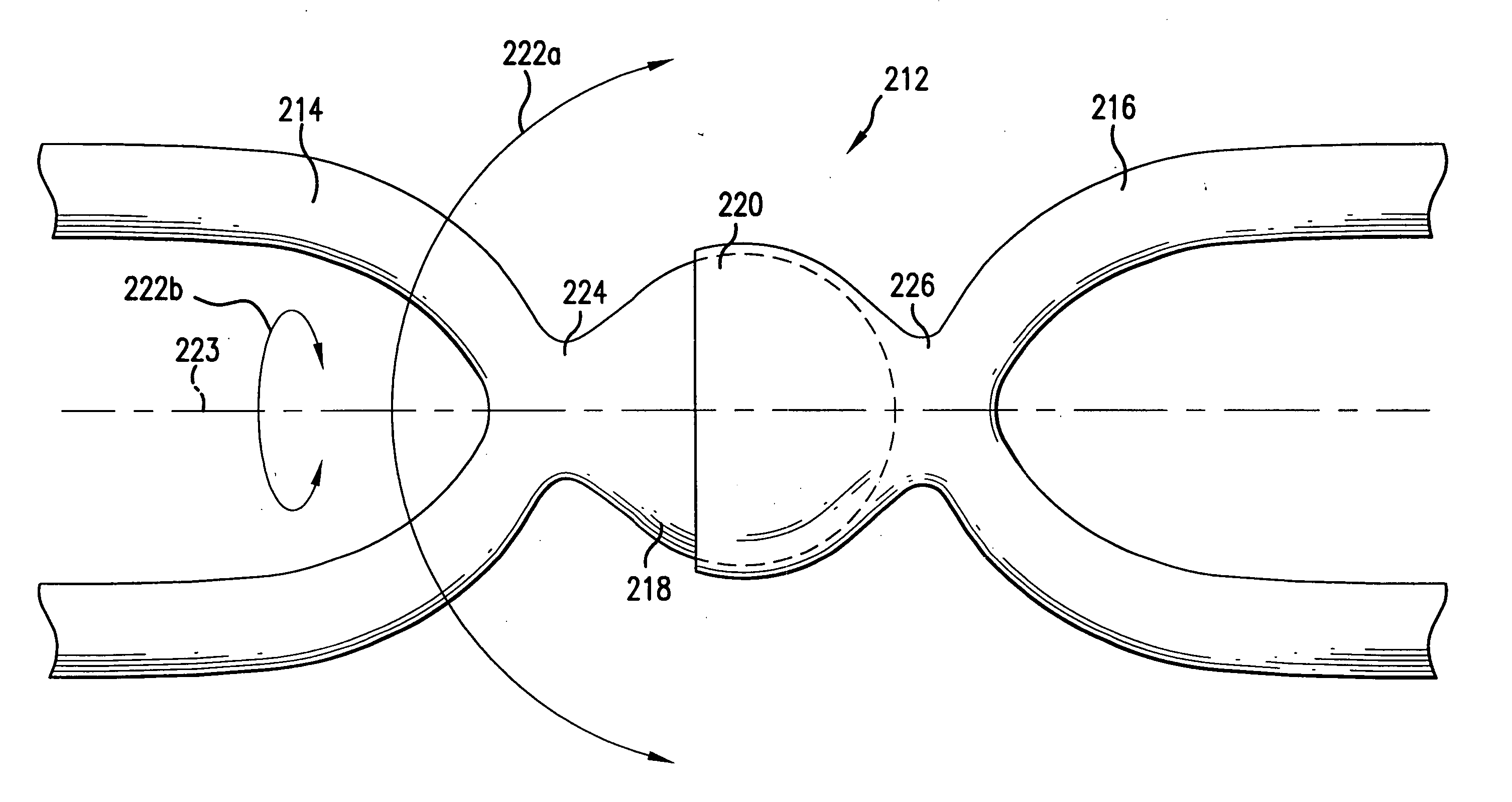
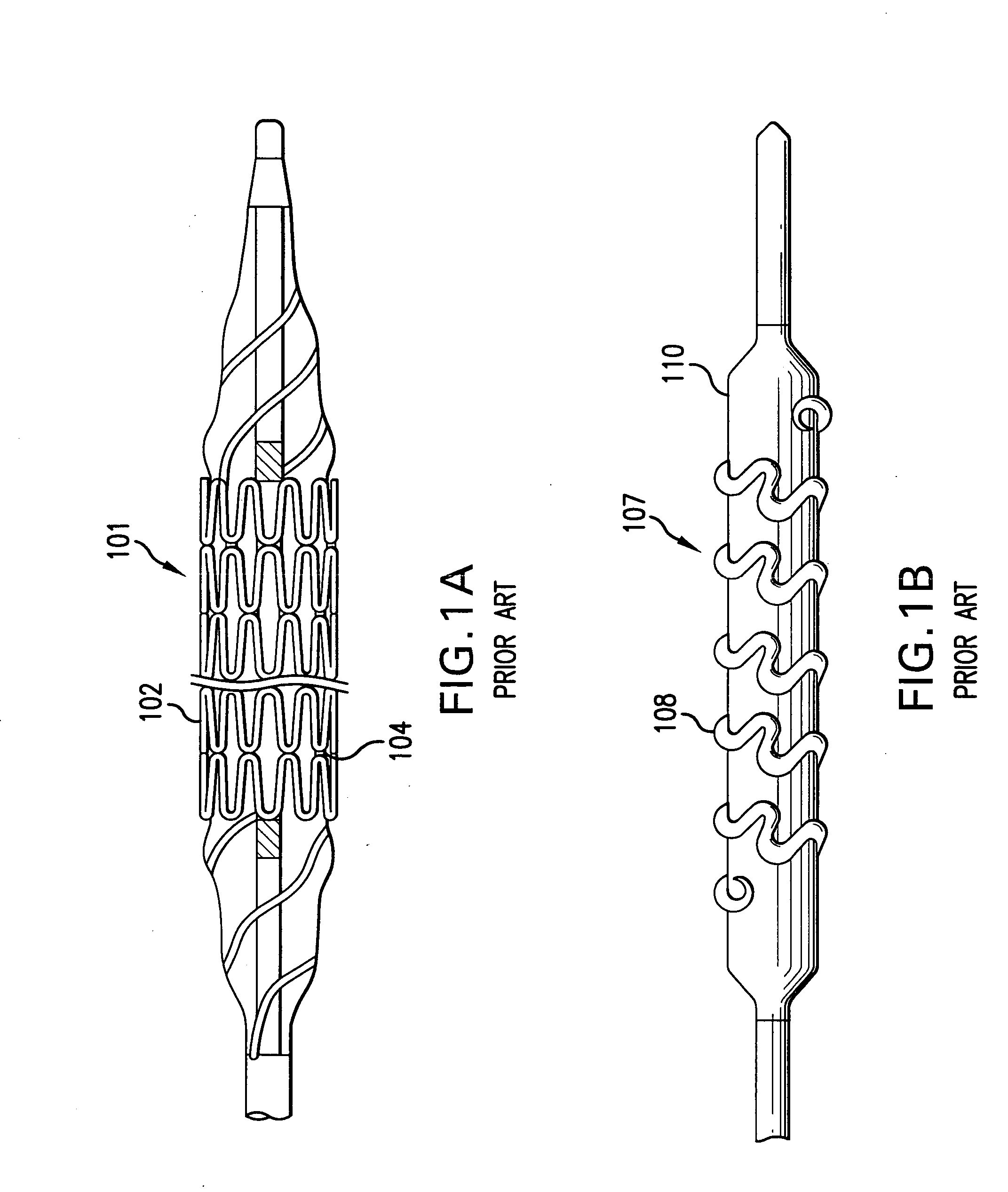
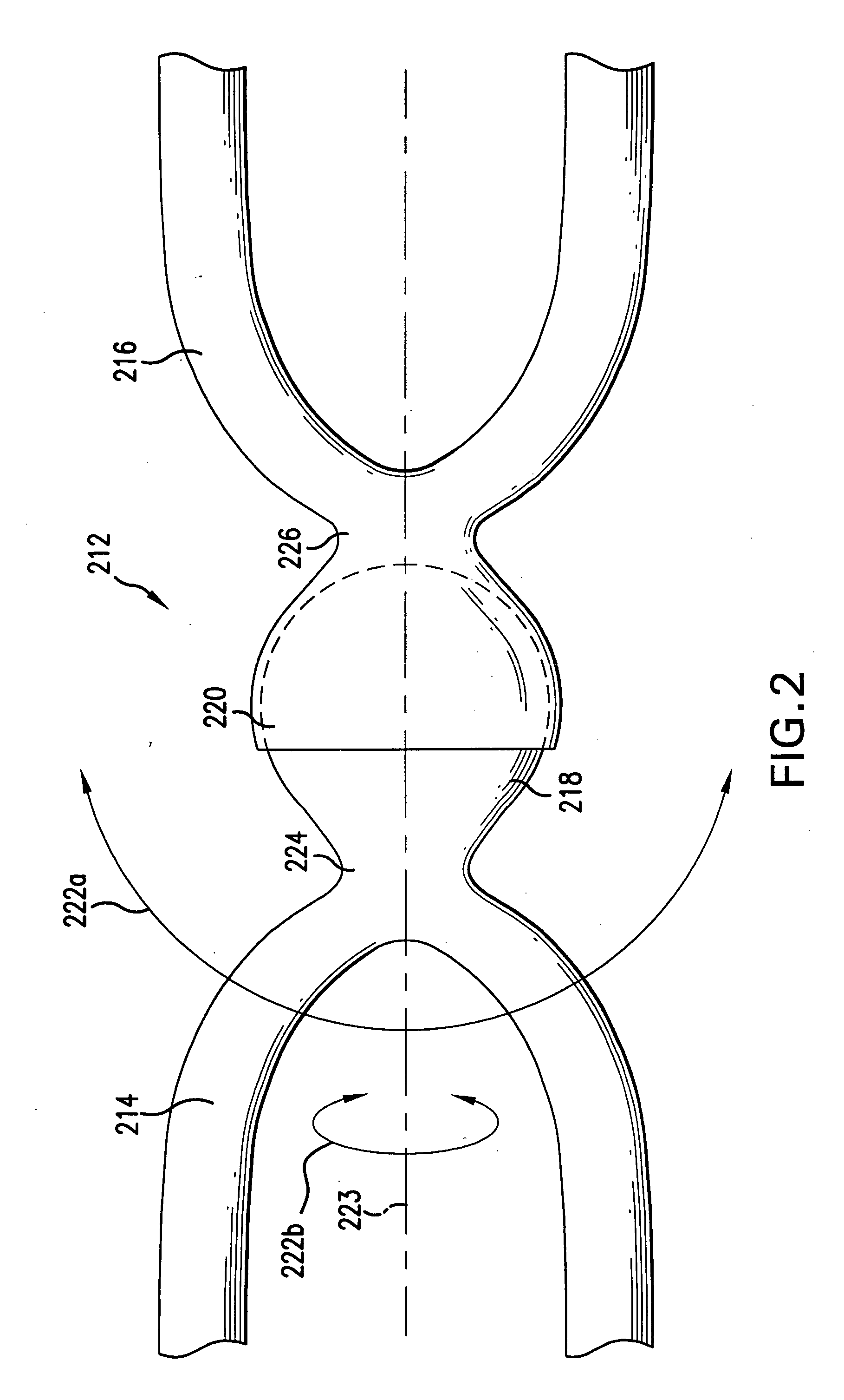
[0034]FIGS. 1A and 1B show stents 101 and 107, respectively, in which the stent body comprises adjacent rows, which may be interconnected. In particular, the rows of stent 101 of FIG. 1A are separate cylindrical segments, which are interconnected by welding a first row directly to a second row, in this case at apexes 104 of sinusoidally shaped segments. FIG. 1B shows rows formed from helical windings 108, in this case of a sinusoidally shaped wire or ribbon. A stent of the present invention has adjacent rows, for example those shown in FIGS. 1A and 1B, with increased flexibility by using various ways of interconnecting adjacent rows. Although FIGS. 1A and 1B show rows that are sinusoidally shaped, the present invention contemplates stents having other overall gen...


PUM


Abstract

A stent device including a stent body having a plurality of adjacent rows and one or more interconnections or interlocking rings between rows. The interconnections have first and second connecting portions with first ends permanently and immovably coupled to the rows and second ends interlocked with each other, such that the second ends of each portion can move independently of the other. The interconnections include ball and socket joints, hinge joints or universal joints. Interlocking rings have indentations for receiving the other ring, such that when interlocked, the rings will lay flat against a body lumen wall.

Description

FIELD OF THE INVENTION [0001] This invention relates generally to a medical device. More specifically, the invention relates to an implantable stent prosthesis for treatment of stenosis in blood vessels BACKGROUND OF THE INVENTION [0002] A wide range of medical treatments have been previously developed using “endoluminal prostheses,” which terms are herein intended to mean medical devices which are adapted for temporary or permanent implantation within a body lumen, including both naturally occurring or artificially made lumens. Examples of lumens in which endoluminal prostheses may be implanted include, without limitation: arteries, such as those located within the coronary, mesentery, peripheral, or cerebral vasculature; veins; gastrointestinal tract; biliary tract; urethra; trachea; hepatic shunts; and fallopian tubes. Various types of endoluminal prostheses have also been developed, each providing a uniquely beneficial structure to modify the mechanics of the targeted lumen wall...

Claims


Application Information

Patent Timeline
IPC IPC(8): A61F2/06A61F2/82
CPCA61F2/91A61F2/915A61F2002/828A61F2230/0054A61F2002/9155A61F2002/91591A61F2/89A61F2002/91533A61F2220/0033
Inventor KANTOR, JOHN D.JONES, RYAN ALEXANDER
Owner MEDTRONIC VASCULAR INC
Why Eureka
Try Eureka