Fuel nature measuring device of internal combustion engine and internal combustion engine having the same

a technology of fuel nature and measuring device, which is applied in the direction of combustion-air/fuel-air treatment, electric control, instruments, etc., can solve the problem of not being able to acquire accurate information between the two, and the problem of not being able to achieve the effect of accurate measuremen

Active Publication Date: 2006-02-09
NIPPON SOKEN +1
View PDF7 Cites 45 Cited by
  • Summary
  • Abstract
  • Description
  • Claims
  • Application Information

AI Technical Summary

Benefits of technology

[0007] The embodiments of the present invention are directed to solve the above-described and other problems and provide a fuel nature measurin...

Problems solved by technology

However, during cold starting with no sufficient warm-up, part of the fuel injected from the fuel injection valve tends to stick to the inner wall surface of the intake port or the surface of the intake valve and fa...

Method used


Image

  • Fuel nature measuring device of internal combustion engine and internal combustion engine having the same
  • Fuel nature measuring device of internal combustion engine and internal combustion engine having the same
  • Fuel nature measuring device of internal combustion engine and internal combustion engine having the same

Examples


first embodiment

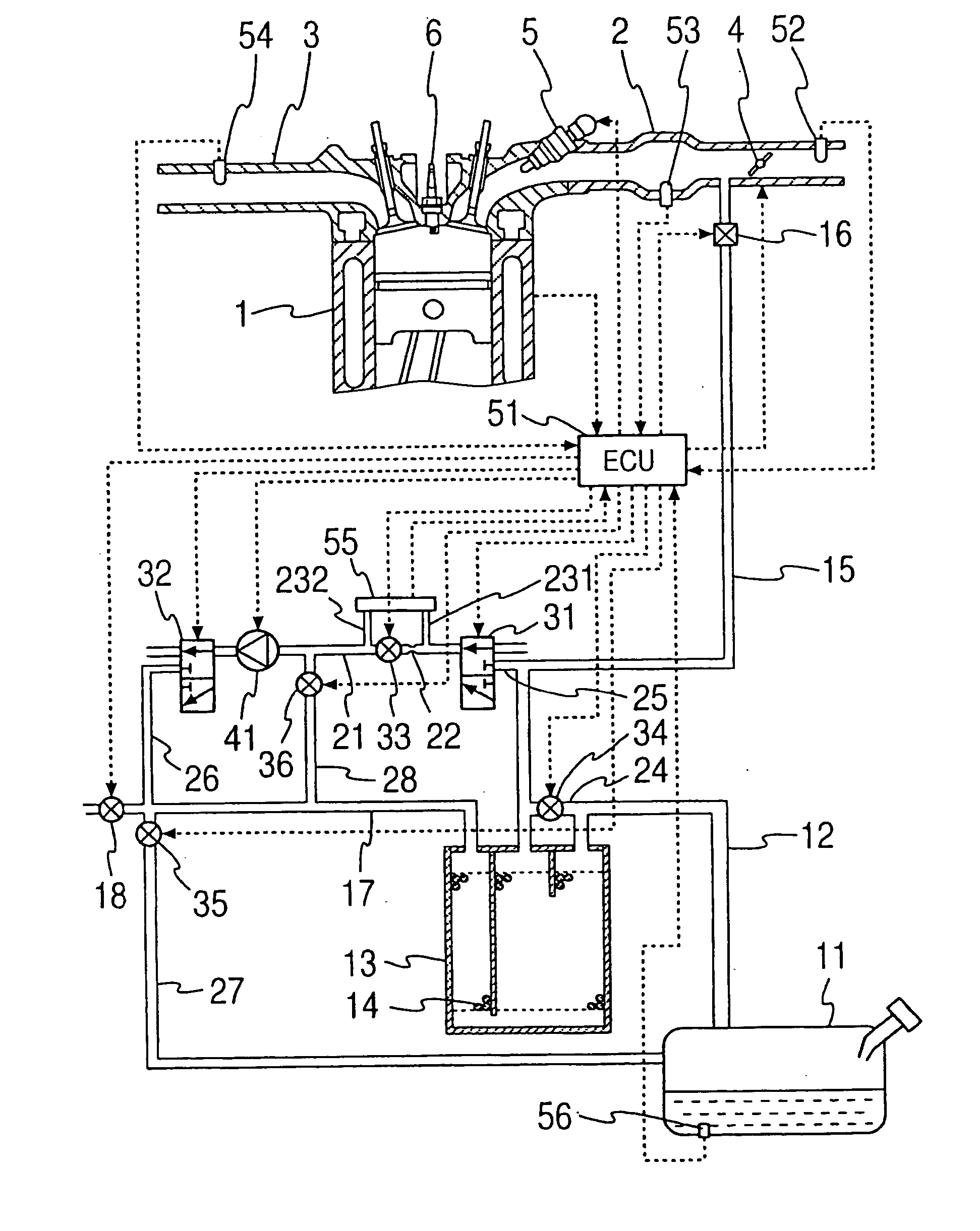
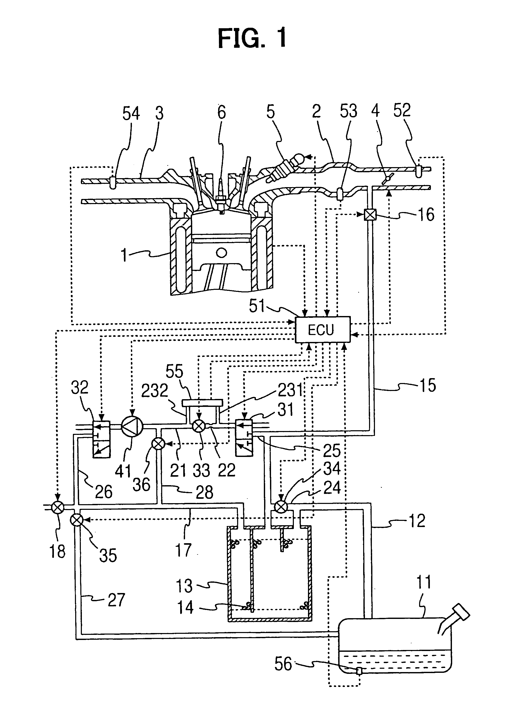
[0052]FIG. 1 illustrates a configuration of a fuel nature measuring device according to the invention installed in an automobile engine. A fuel tank 11 for an internal combustion engine 1 is connected to a canister 13 through a conduit 12, and the fuel tank 11 and the canister 13 are continuously in communication. The canister 13 is filled with an absorbent 14 and the fuel evaporated in the fuel tank 11 is temporarily absorbed by the absorbent 14. The canister 13 is connected to an intake pipe 2 of the engine 1 through a purge passage 15. The purge passage 15 is provided with a purge valve 16 serving as a purge control valve, and when the valve opens, the canister 13 and the intake pipe 2 communicate.

[0053] The purge valve 16 is an electromagnetic valve and has its valve travel controlled by duty control or the like using an electronic control unit (ECU) 51 that controls various parts of the engine 1. Evaporated fuel desorbed from the absorbent 14 is purged into the intake pipe 2 by...

fifth embodiment

[0103] Note that if the elapsed time after the previous concentration detection is greater than or equal to the prescribed time period, the ignition key must be on even at a temperature that is greater than or equal to the prescribed temperature T0. This is because the fuel is not injected during the ignition-off period, the result of fuel nature measuring process is not used for controlling the engine, and the power can be saved during the period. However, if the power consumption can be ignored, the operation may be carried out during the ignition-off period as will be described below in the

[0104]FIG. 14 shows a fuel nature measuring device according to a fourth embodiment of the present invention. The fourth embodiment is substantially the same as the first embodiment except for a part of the configuration. The elements of the fourth embodiment that are substantially the same as those of the first embodiment are denoted by the same reference characters, while the different elemen...


PUM


Abstract

A fuel nature measuring device for measuring the nature of fuel stored in a fuel tank includes a measurement passage, a gas flow generator, a pressure detector, an concentration operator, a temperature detector, and a volatility calculator. The measurement passage has an orifice. The gas flow generator generates gas flow in the measurement passage. The pressure detector detects a differential pressure between opposite ends of the orifice. The concentration operator determines a concentration of evaporated fuel in the fuel tank based on the differential pressure detected when the opposite ends of the measurement passage communicate with the fuel tank and the fuel flows in the measurement passage. The temperature detector determines a temperature of the fuel in the fuel tank. The volatility calculator calculates a volatility of the fuel in the fuel tank based on the concentration of the evaporated fuel and the temperature of the fuel in the tank.

Description

CROSS REFERENCE TO RELATED APPLICATIONS [0001] This application is based upon and claims the benefit of priority of Japanese Patent Application No. 2004-230997, filed on Aug. 6, 2004, the contents of which are incorporated herein by reference. FIELD OF THE INVENTION [0002] The present invention relates to a fuel nature measuring device for an internal combustion engine and an internal combustion engine having the same. BACKGROUND OF THE INVENTION [0003] A gasoline engine in an automobile generally has a fuel injection valve provided at an intake pipe, and fuel injected from the fuel injection valve is supplied to an intake port. However, during cold starting with no sufficient warm-up, part of the fuel injected from the fuel injection valve tends to stick to the inner wall surface of the intake port or the surface of the intake valve and fails to enter the combustion chamber. This substantially reduces the injection amount. In order to secure an air-fuel ratio equivalent to that in ...

Claims


Application Information

Patent Timeline
IPC IPC(8): G06F19/00G01L3/26F02M25/08F02D45/00
CPCF02D41/0045F02D2200/0602F02D2200/0606G01N33/22F02M25/0818G01N7/00F02D2200/0612
Inventor AMANO, NORIYASUKAWANO, TAKANOBUKOYAMA, NOBUHIKO
Owner NIPPON SOKEN
Why Eureka
Try Eureka