

Device for arresting the propagation of a buckle in a double-walled pipe
a technology of double-walled pipes and buckles, which is applied in the direction of sewer pipelines, manufacturing tools, other domestic objects, etc., can solve the problems of virtually impossible, no solution or effective for arresting buckles, and likely buckles, and achieves simple production, long or short cure time
- Summary
- Abstract
- Description
- Claims
- Application Information
AI Technical Summary
Benefits of technology
Problems solved by technology
Method used
Image

Examples
Embodiment Construction
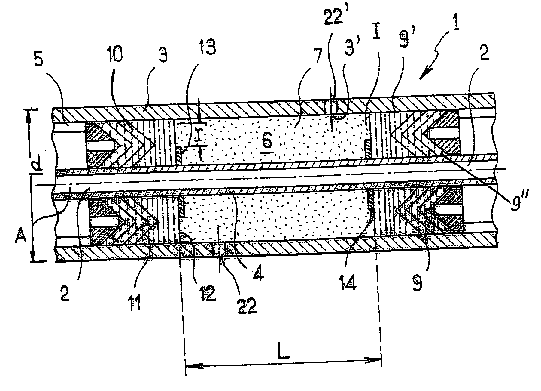
[0031] The double-walled rigid pipe 1 of longitudinal axis A, shown partially in FIG. 1, comprises an inner wall or inner pipe 2 (flow pipe), the diameter and the nature of the material of which are chosen according to the fluid flowing in the said inner pipe, especially depending on the temperature and pressure of the fluid, and an outer wall or outer pipe 3 (carrier pipe) which is slipped over the inner pipe 2. The outer pipe 3 generally has an outside diameter D which is oversized with respect to the inner pipe 2 in order to allow a thermal insulation to be placed in the annular space 5 and represents a thickness allowing the hydrostatic pressure that is exerted on the said outer pipe 3 to be withstood. The rigid pipe 1 generally includes spacers or separators (not shown) which are fastened to the external surface 4 of the inner pipe 2 and which are lodged in the annular space 5 provided between the outer pipe 3 and the inner pipe 2.
[0032] According to the invention, a curable c...
PUM
| Property | Measurement | Unit |
|---|---|---|
| Temperature | aaaaa | aaaaa |
| Length | aaaaa | aaaaa |
| Diameter | aaaaa | aaaaa |
Abstract
Description
Claims
Application Information