40 mm low cost cartridge

a cartridge and low-cost technology, applied in the direction of cartridges, weapons, ammunition projectiles, etc., can solve the problems of holding down manufacturing costs, known practice cartridges have a relatively expensive design with rotating parts, etc., and achieve the effect of greatly simplifying the manufacture of rounds

Active Publication Date: 2006-02-16
NICO PYROTECHNIK HANNS JUERGEN DIERGEN
View PDF5 Cites 46 Cited by
  • Summary
  • Abstract
  • Description
  • Claims
  • Application Information

AI Technical Summary

Benefits of technology

[0005] The invention is based on the object of providing a design for a cartridge practice round of the type described above, by means of which the manufacture of rounds is greatly simplified.

Problems solved by technology

This and other known practice cartridges have a relatively expensive design with rotating parts, machine-drilled bores, rifling, etc.
Manufacturing costs may be held down since such practice cartridges may be produced in large quantities.

Method used


Image

  • 40 mm low cost cartridge
  • 40 mm low cost cartridge
  • 40 mm low cost cartridge

Examples


Embodiment Construction

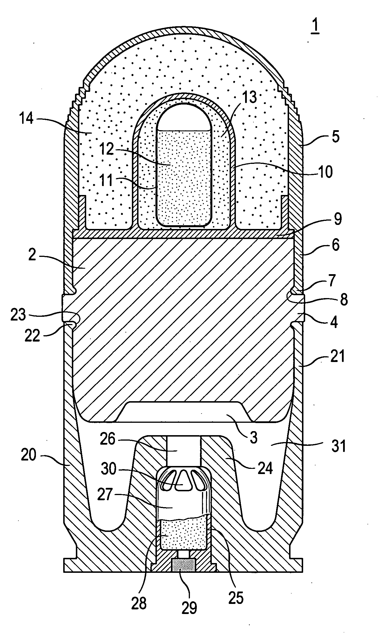
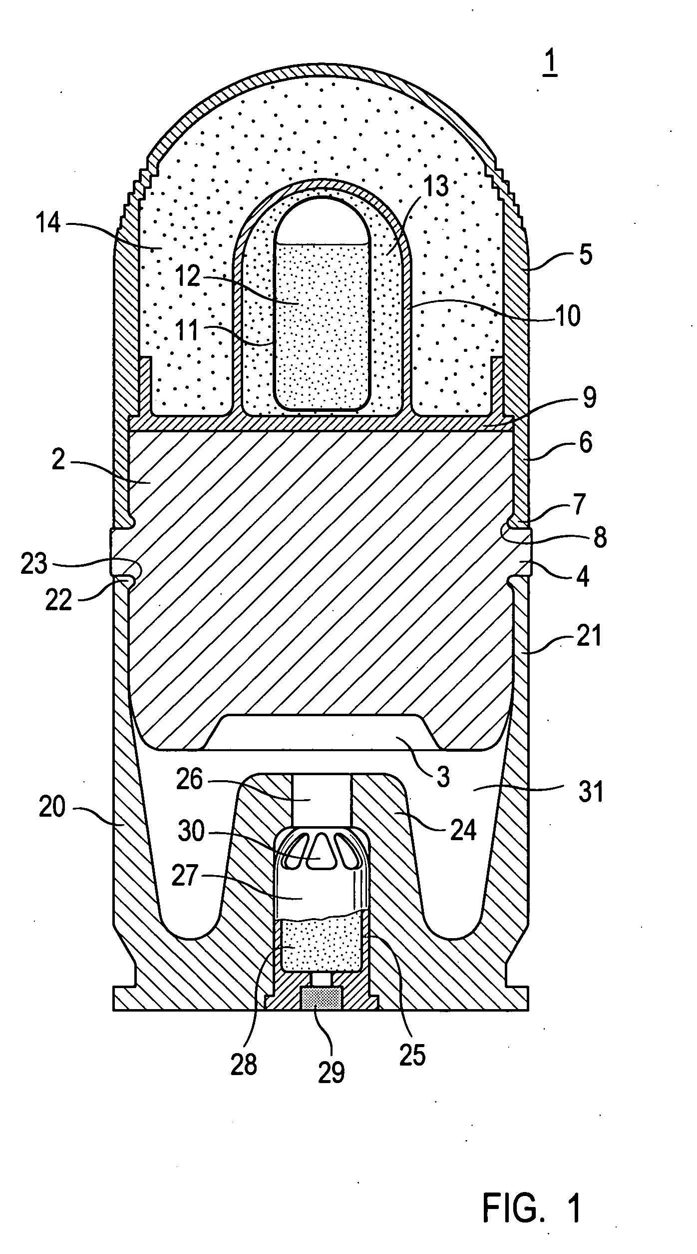
[0009] The projectile for the cartridge practice round according to the invention includes a cylindrical central body with two faces whereby the first, lower face forms the base of the projectile. Further, a one-piece projectile tip is provided in the shape of, for example, a hood that becomes a spring collar on its lower end facing the central body. The lower, open end of this spring collar is provided with an inner circumferential engagement element. The collar of the projectile tip is pressed onto the side opposite the projectile base onto the circumference of the central body whereby the first engagement element of the tip collar fits into a corresponding second engagement element of the central body, locking the central body to the projectile tip.

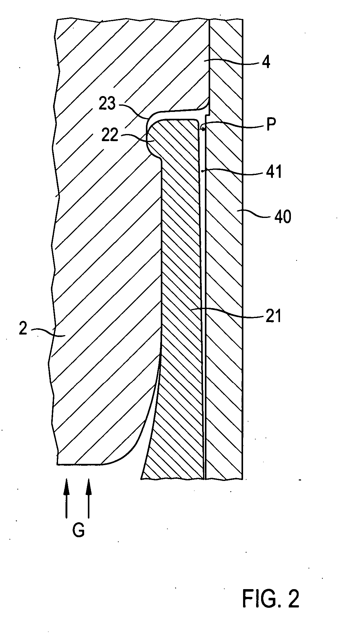
[0010] The cartridge shell is of one piece, and is shaped approximately as a cylindrical basin whose upper, open end side wall facing the central body transforms in its upper area into spring-elastic collar that is provided at the upp...


PUM


Abstract

The cartridge-type training round consists of a projectile and a cartridge shell into which the projectile is inserted. The projectile includes a one-piece cylindrical central body (2) and a one-piece basin-shaped projectile tip (5) that is pressed onto the central body and engages a circumferential engagement bead (7) with a circumferential engagement slot (8) located in the central body (2). The cartridge shell (20) is a one-piece basin-shaped part; it is also pressed onto the central body (2) and engages a circumferential engagement bead (22) with a circumferential engagement slot (23) of the central body (2). A receiver recess (25) is provided in an approximately cylindrical projection (24) that is inserted centered from the base to receive the propulsive charge (28) and its igniter (29). The round is of simple design, and may be manufactured inexpensively owing to its simple parts that may be largely of plastic without loss of function.

Description

SCOPE OF THE INVENTION [0001] The invention relates to a cartridge consisting of a projectile and a cartridge shell surrounding this projectile, whereby the cartridge consisting of projectile and cartridge shell is suitable for use in a long-barreled weapon, especially one of medium caliber, e.g., 40 mm. The projectile includes a projectile body with a projectile tip and a projectile base; a charge chamber containing a propulsion charge is provided within the cartridge shell that may be ignited via a pyrotechnic igniter. [0002] The projectile and the cartridge shell are joined mechanically—e.g., threaded, crimped, etc., whereby this connection may also be designed as an intentional break point. [0003] After the propulsive charge is ignited, it burns rapidly, whereby the propulsive gases so developed create high pressure within the propulsion chamber that acts on the base of the projectile; the mechanical connection between cartridge shell and projectile breaks at a pre-determined pr...

Claims


Application Information

Patent Timeline
Patent Type & Authority Applications(United States)
IPC IPC(8): F42B8/00F42B14/06F42B5/02F42B5/30F42B8/02F42B8/12
CPCF42B8/02F42B12/40F42B8/16F42B5/02F42B5/30F42B8/12
Inventor HAESELICH, DETLEF
Owner NICO PYROTECHNIK HANNS JUERGEN DIERGEN
Why Eureka
Try Eureka