Optical product cure oven

a technology of optical products and ovens, applied in the field of systems, apparatus, and methods for curing optical components, can solve the problems of large care, small amount of air, and large care requirements of systems and methods for manufacturing certain products, such as optical products and related subcomponents, and achieve the effect of increasing the ra

Active Publication Date: 2006-02-16
II VI DELAWARE INC
View PDF2 Cites 7 Cited by
  • Summary
  • Abstract
  • Description
  • Claims
  • Application Information

AI Technical Summary

Benefits of technology

[0016] The present invention solves one or more of the foregoing problems in the prior art with systems, apparatus, and methods for curing adhesives efficiently at a relatively higher rate than otherwise possible. In particular, an oven can be configured to cure two or more optical subcomponents of an optical assembly at a certain pressure, such that the two subcomponents adhere to one another without being broken apart.

Problems solved by technology

Presently, systems and methods for manufacturing certain products, such as optical products and related subcomponents, can require great care, and can take a relatively long time.
In some cases, these subcomponents are assembled together using specialized epoxies that can create unique constraints.
Unfortunately, when an optical component is placed inside an optical barrel containing epoxy, a small amount of air (e.g., space 106) becomes trapped between the optical subcomponent and the first sealed end of the barrel cavity.
In one scenario, air expansion may force the less-viscous epoxy to ooze out of the assembled OSA 117 during the curing process, such that there is insufficient epoxy to form a bond between the optical subcomponent and the OSA barrel.
For example, an epoxy that is very strong and resilient to certain environmental factors may take tens of hours to properly cure at room temperature.
Unfortunately, the types of epoxies used for bonding conventional optical components—as well as the rather small, precisely aligned optical component parts—do not lend to speeding up the curing process with added heat.
Thus, conventional methods for curing epoxies in optical components often involve rather long two-step processes.
Unfortunately, the time it takes for conventional optical epoxies to harden sufficiently at room temperature can be anywhere from approximately 12 hours to approximately 30 hours, depending in part on the heat resistance of the given epoxy.
Other conventional curing processes can reduce the overall cure time for the epoxy, but nevertheless increase the number of required production steps.
Unfortunately, perforating an OSA barrel sometimes requires an additional processing step after the OSA barrel has been manufactured.
Furthermore, since perforations can open the optical subcomponents to water (or humidity) damage, the manufacturer may still need to cover the perforations in some way after the epoxy cures.
As such, perforating one or more subcomponents to release expanding air during a curing process can be fairly inefficient, or can lead to lower quality OSAs.

Method used


Image

  • Optical product cure oven
  • Optical product cure oven
  • Optical product cure oven

Examples


Embodiment Construction

[0025] The present invention extends to systems, apparatus, and methods for curing adhesives efficiently at a relatively higher rate than otherwise possible. In particular, an oven can be configured to cure two or more optical subcomponents of an optical assembly at a certain pressure, such that the two subcomponents adhere to one another without being broken apart.

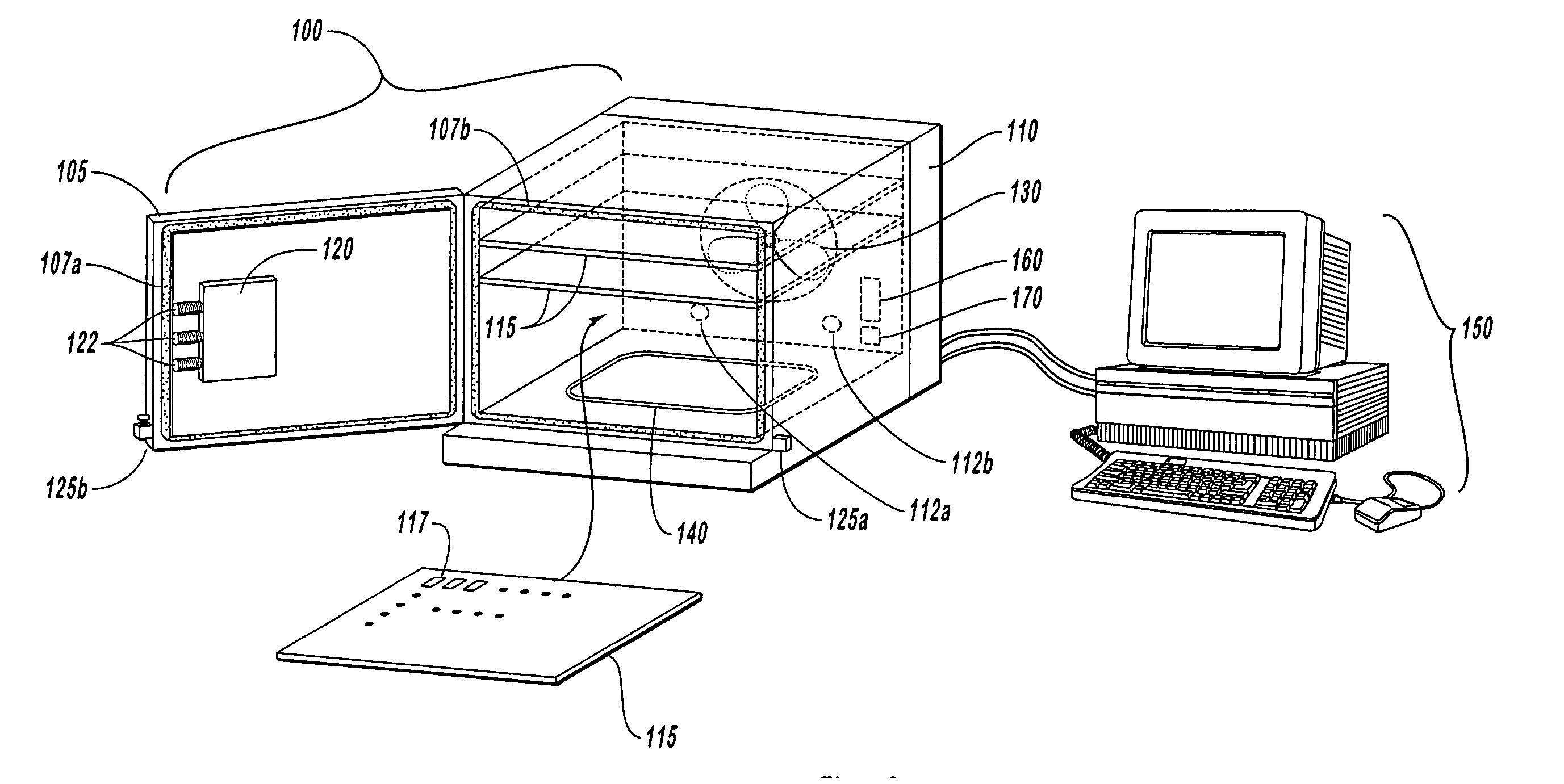
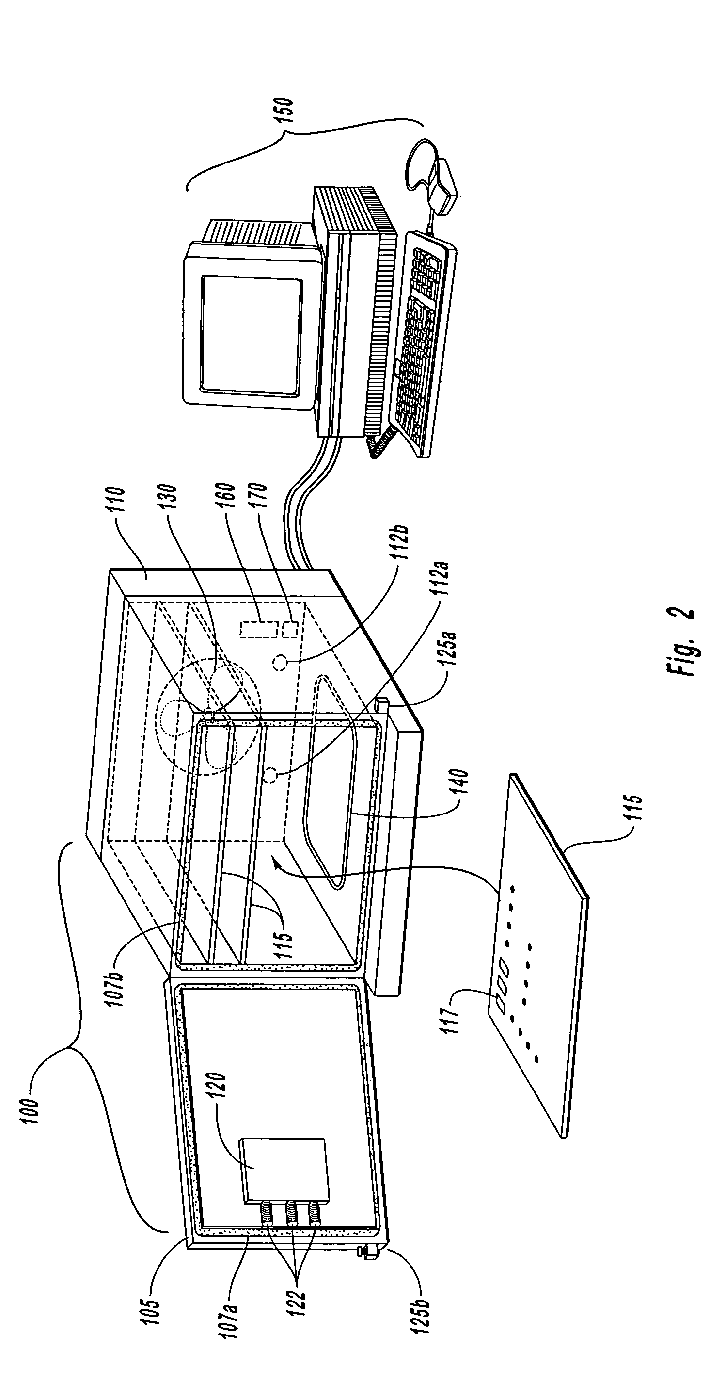
[0026] In particular, FIG. 2 illustrates one implementation of a system for curing adhesives, such as epoxy adhesives, used to assemble optical subcomponents. As shown, an exemplary system can comprise a cure oven 100 that is configured to adjust internal pressure inside the cure oven 100 chamber while adjusting heat to a critical temperature. As will be understood from the present specification and claims, the system is designed in such a way that assembled optical subcomponents can be cured rapidly and efficiently.

[0027] In one implementation, an exemplary cure oven 100 comprises a steel, inner chamber that is approxi...


PUM

PropertyMeasurementUnit
temperatureaaaaaaaaaa

Abstract

A cure oven comprises a sealable door and one or more pressure valves mounted inside for curing optical subcomponents that have been assembled using an adhesive. The cure oven comprises a chamber that can be configured to receive several hundreds of assembled optical subcomponents. The cure oven is further coupled to a computerized system via a drive motor. The computerized system initiates the heating and cooling sequences, and indicates whether the door can be opened, or must remain shut. The cure oven maintains a certain pressure inside the oven chamber consistent with a rise in temperature, allowing assembled optical subcomponents to be cured at a much higher rate than possible without disassembling, or being damaged.

Description

CROSS-REFERENCE TO RELATED APPLICATIONS [0001] The present invention claims the benefit of priority to U.S. Provisional Patent Application No. 60 / 592,665, filed on Jul. 30, 2004, entitled “OPTICAL PRODUCT CURE OVEN”, the entire contents of which are incorporated herein by reference.BACKGROUND OF THE INVENTION [0002] 1. The Field of the Invention [0003] The present invention relates to systems, apparatus, and methods for curing optical components, such as optical assembly components that may be used in an optical transceiver. [0004] 2. Background and Relevant Art [0005] Presently, systems and methods for manufacturing certain products, such as optical products and related subcomponents, can require great care, and can take a relatively long time. For example, form factor optical transceivers (e.g., SFF, SFP, XFP, etc.) can comprise several subcomponents that require precision instrumentation, or simply exercising a high degree of care, when aligning or assembling the subcomponents to...

Claims


Application Information

Patent Timeline
Patent Type & Authority Applications(United States)
IPC IPC(8): B32B37/00
CPCF27B17/0016F27D19/00F27D2021/0007F27D2019/0003F27D2019/0006F27D21/0014
Inventor GILKERSON, JACK A.JANNATI, MANSOURJOHNSON, CHRISTOPHER W.
Owner II VI DELAWARE INC
Why Eureka
Try Eureka