Optical fiber, optical fiber ribbon, and optical interconnection system

Inactive Publication Date: 2006-02-16
FURUKAWA ELECTRIC CO LTD
View PDF6 Cites 39 Cited by
  • Summary
  • Abstract
  • Description
  • Claims
  • Application Information

AI Technical Summary

Problems solved by technology

The electrical transmission has a problem with electrical crosstalk due to high density wiring as well as recent high CPU clock speed, thereby requiring specific applications such as reshaping.

Method used


Image

  • Optical fiber, optical fiber ribbon, and optical interconnection system
  • Optical fiber, optical fiber ribbon, and optical interconnection system
  • Optical fiber, optical fiber ribbon, and optical interconnection system

Examples


Embodiment Construction

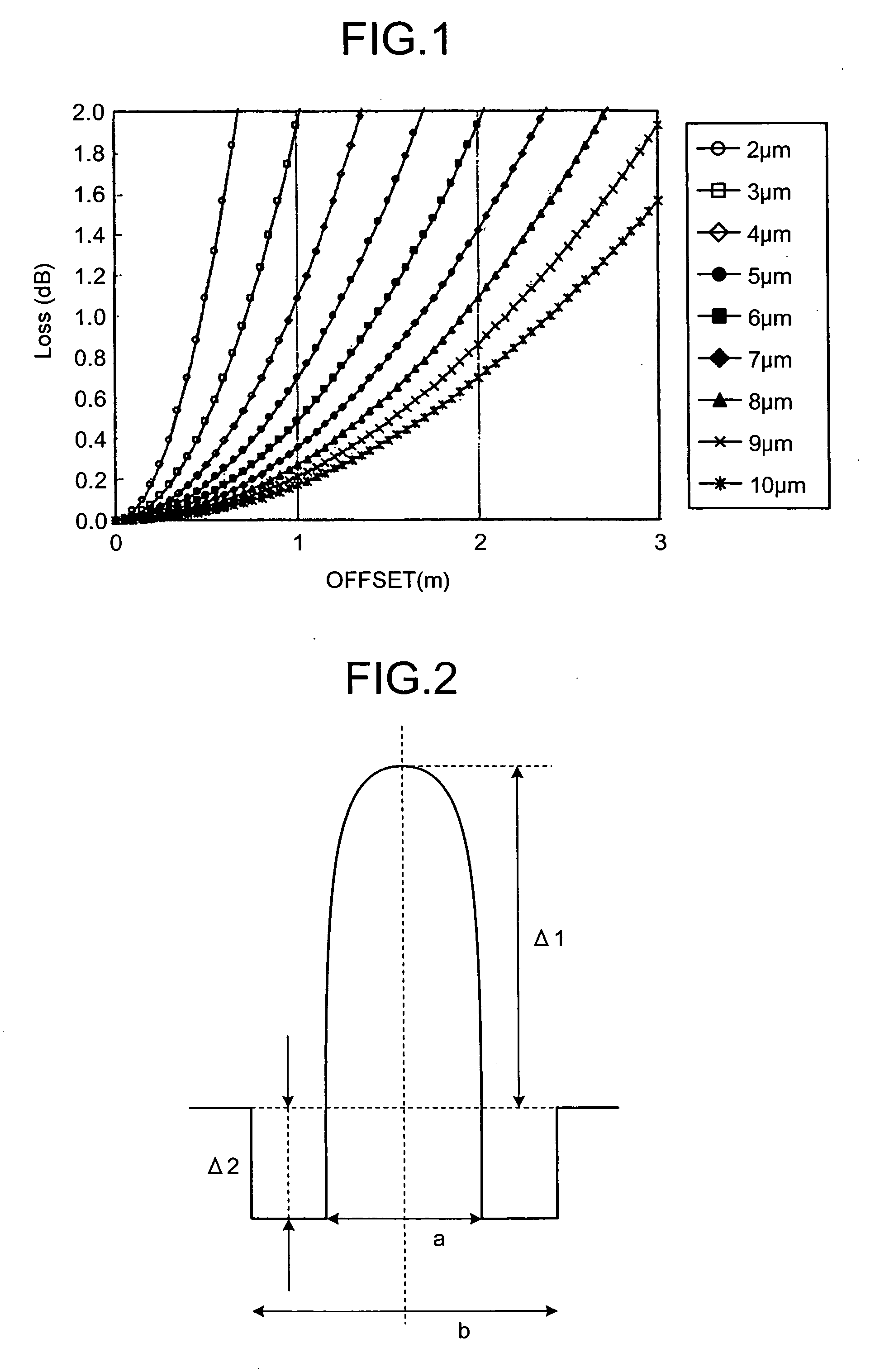
[0022] An SMF fiber generally has a core diameter of 5 to 10 μm, which is smaller than a core diameter of 50 to 62.5 μm of an MMF fiber, and hence requires an accurate connection between the fiber and other optical element such as a light source. Moreover, a communication system in equipment through an optical interconnection sometimes requires almost ten spatial connections between optical elements such as optical fibers and VCSELs with connectors. The connection between the optical elements through spatial connections cause offsets between coupling parts, thereby causing a splicing loss. Accordingly, the offset causes the splicing loss even if mode field diameters (MFDs) among the elements are the same. The more an MFD difference between the coupling elements, the less the coupling efficiency in offset, in other words the splicing loss for the offset tends to increase.

[0023]FIG. 1 shows calculated values of a splicing loss with respect to an offset for a connection between the sa...


PUM


Abstract

An optical fiber includes a core and a cladding which are made from silica glass, allows single mode transmission at a wavelength of 1100 nm, and has a mode field diameter of not less than 4 μm at a wavelength of 1100 nm, and a bending loss of not more than 1 dB per turn with a curvature radius of 1 mm at a wavelength of 1100 nm.

Description

BACKGROUND OF THE INVENTION [0001] 1. Field of the Invention [0002] The present invention relates to an optical fiber, and, more particularly to an optical fiber and an optical fiber ribbon for optical wiring in equipment, ribbon and an optical interconnection system using the optical fiber or the optical fiber ribbon. [0003] 2. Description of the Related Art [0004] There are two types of signal transmission in equipment, electrical transmission and optical interconnection. The electrical transmission has a problem with electrical crosstalk due to high density wiring as well as recent high CPU clock speed, thereby requiring specific applications such as reshaping. As a result, the electrical transmission, when used as a signal transmission in equipment, allows a transmission range of at most 100 meters and a transmission rate of at most 10 Gbps. On the other hand, the optical interconnection, when used as a signal transmission in equipment, allows extreme broadband transmission as c...

Claims


Application Information

Patent Timeline
Patent Type & Authority Applications(United States)
IPC IPC(8): G02B6/036G02B6/02G02B6/028G02B6/44
CPCG02B6/0281G02B6/0288G02B6/4436G02B6/03644G02B6/0365G02B6/03627
Inventor SAKO, AKIFUMISUGIZAKI, RYUICHIYAGI, TAKESHI
Owner FURUKAWA ELECTRIC CO LTD
Why Eureka
Try Eureka