
Method and system for providing a signature signal in an optical network in the event of loss of a client

a signature signal and optical network technology, applied in the field of optical communication systems, can solve problems such as system alarms, loss of client signals, and multiple nodes in the optical network

Inactive Publication Date: 2006-02-16
ALCATEL LUCENT CANADA
View PDF11 Cites 10 Cited by
  • Summary
  • Abstract
  • Description
  • Claims
  • Application Information

AI Technical Summary

Benefits of technology

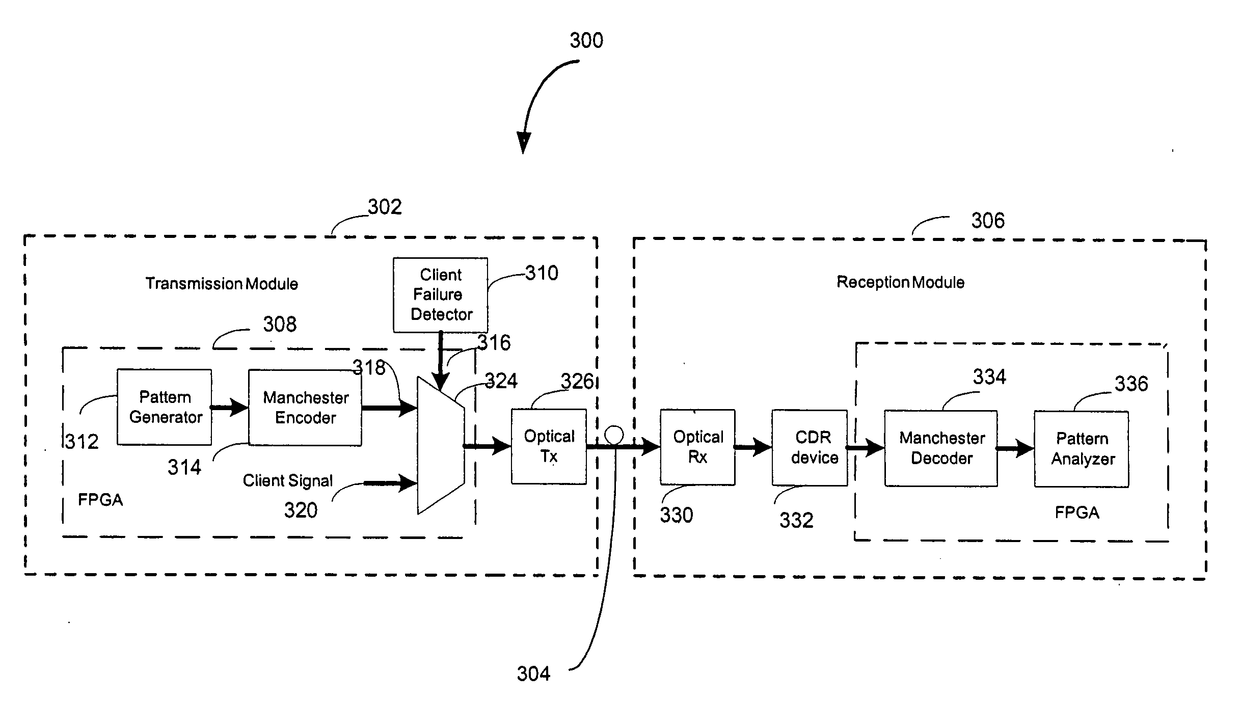
[0011] A system for providing a Signature signal in an optical network in the event of failure of a client, the optical network contains channels, each having a unique tag in a form of a low frequency dither tone modulation called Wavekey generated by a Wavelength Tracker technology, the system comprising: a transmission module for generating and transmitting t...

Problems solved by technology

An optical network consisting of multiple nodes is subject to intermittent faults that may raise alarms in the system.
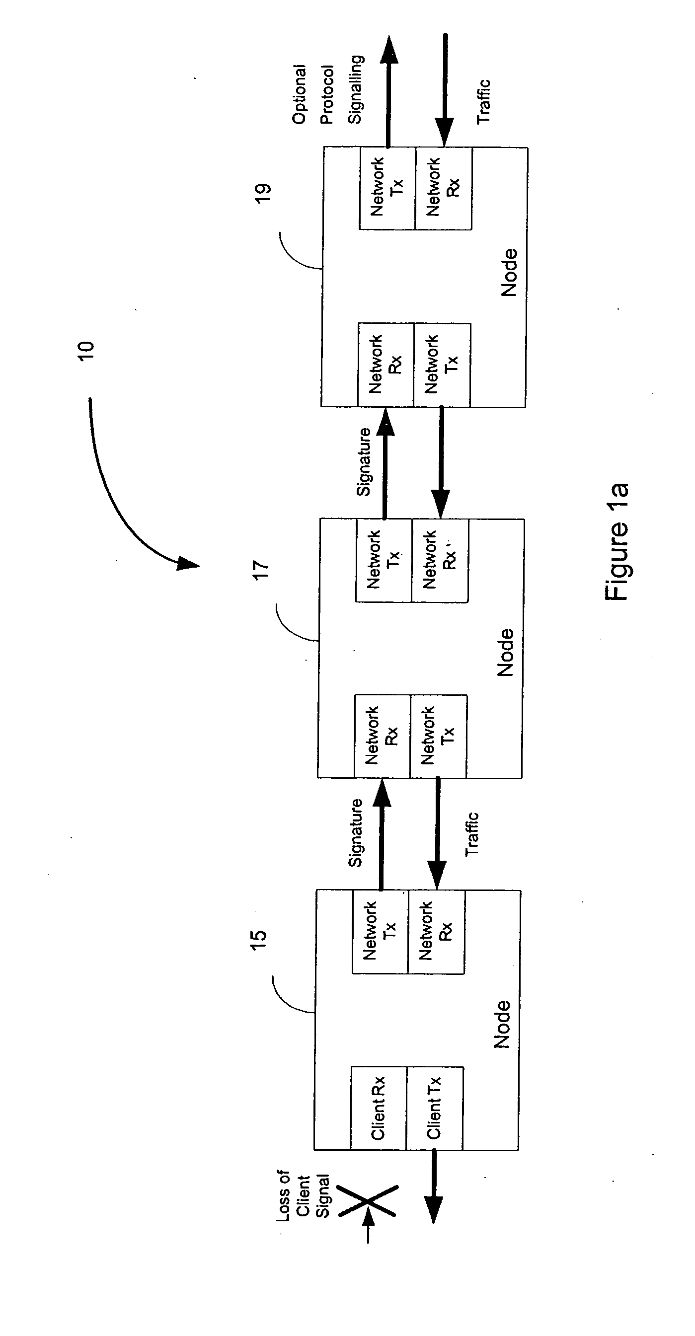
A single fault such as a client failure at a node in the network can, however, give rise to loss of client signal leading to multiple alarms detected at multiple points.
Although simple, such an approach leads to the loss of optical power and can give rise to a multitude of alarms as well as loss of Clock and Data Recovery (CDR) locks at downstream nodes in the network.
Although optical power is maintained the CDR lock is lost and multiple alarms may be raised at downstream nodes.
Examining all the raised alarms and determining the root cause alarm that leads to the solution of the actual problem that has occurred on the system is a difficult and time-consuming task.
This in turn can significantly increase the time required for returning service to the network element.

Method used


Image

  • Method and system for providing a signature signal in an optical network in the event of loss of a client
  • Method and system for providing a signature signal in an optical network in the event of loss of a client
  • Method and system for providing a signature signal in an optical network in the event of loss of a client

Examples


Embodiment Construction

[0021] Wavelength Tracker is a technology that traces the end-to-end path and power level of the signal on each wavelength and is developed by Tropic Network. A light path to be monitored on an optical network can be identified by using Wavelength Tracker. The Wavelength Tracker technology applies a unique optical tag to each wavelength (channel) at the Dense Wavelength Division Multiplexing (DWDM) layer. The unique optical tag includes a low frequency modulation of one or more dither tones onto the optical channel, which uniquely identify the optical channel. This optical tag (also called a Wavekey) is applied to the optical channel at the source node of the light path. The optical tag is detectable at intermediate nodes on the light path via inexpensive decoders present on line cards. Detection of the optical signature is accomplished without an Optical-Electrical-Optical (OEO) conversion at intermediate nodes, thus resulting in a cost-effective solution. Wavelength Tracker techno...


PUM


Abstract

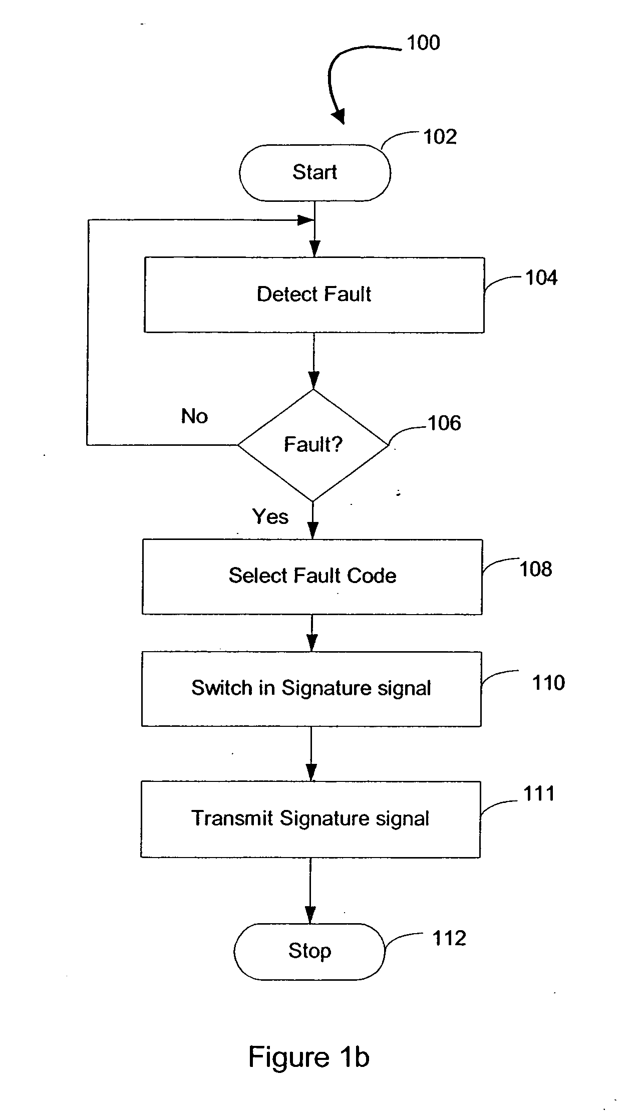
An optical network including multiple nodes is subject to intermittent faults that may raise alarms in the system. The invention focuses on an optical network based on the Any rate architecture. A single fault such as a client failure at a node in such a network can give rise to a loss of client signal leading to multiple alarms detected at multiple points. To alleviate this problem this invention provides switching in a special Signature signal in place of the lost client signal. By detecting the Signature signal containing a specific code, the fault on the any rate-based architecture can be uniquely identified. In addition to fault identification, the Signature signal on the network makes it possible to maintain Clock and Data Recovery Locks at downstream nodes. The Signature signal serves also as a vehicle for carrying a special optical tag called Wavekey provided by the Wavelength Tracker technology developed by the Applicant. This optical tag includes a low frequency modulation of one or more dither tones onto an optical channel, which is uniquely identified by the tag. Maintaining the Wavekey is important for tracing the end-to-end path and power level of the signal on each wavelength. A method and a Field Programmable Gate Array-based system for the generation and identification of such a Signature signal that not only identifies the fault that has occurred on the optical network but also provides for the maintenance of the Wavekey, are described.

Description

FIELD OF INVENTION [0001] The invention relates to optical communication systems, and in particular to a method and system for incorporating a specific Signature signal in an optical network when a client failure occurs, for reducing alarm propagation in an optical network. BACKGROUND OF INVENTION [0002] An optical network consisting of multiple nodes is subject to intermittent faults that may raise alarms in the system. The invention focuses on an optical network based on the Any rate architecture. The need for an Any rate solution to seamlessly transport less common protocols within traditional telecommunication based metropolitan area network has been well established over the past decade by major carriers. On such an enclosed network that does not have any vendor mid-span meet within the network, it is possible to support a variety of native protocols. A single fault such as a client failure at a node in the network can, however, give rise to loss of client signal leading to mul...

Claims


Application Information

Patent Timeline
IPC IPC(8): G02F1/00
CPCH04L41/06H04B10/00
Inventor HOLMES, DAVID MICHAEL RYANREEPSCHLAGER, PAUL MARK
Owner ALCATEL LUCENT CANADA
Learn More