Carbon nanotube-based device and method for making the same

a carbon nanotube and device technology, applied in the direction of carbonsing rags, aligned nanotubes, transportation and packaging, etc., can solve the problems of limited range of different kinds of carbon nanotube-based devices, difficult to apply the method of controlling the growth direction of carbon nanotubes in generating localized complex structures, etc., to achieve the effect of slowing down the growth of carbon nanotubes

Active Publication Date: 2006-02-16
TSINGHUA UNIV +1
View PDF4 Cites 47 Cited by
  • Summary
  • Abstract
  • Description
  • Claims
  • Application Information

AI Technical Summary

Benefits of technology

[0007] However, carbon nanotubes of all the carbon nanotube based structures obtained by the above-mentioned methods are aligned along a linear direction, and / or extend perpendicularly from the substrates. Furthermore, the method of using an external electric field to control a direction of growth of the carbon nanotubes is difficult to apply in generating localized complicated structures with plural orientations of the carbon nanotubes. Accordingly, the range of diversity of different kinds of carbon nanotube-based devices is limited.

Problems solved by technology

Furthermore, the method of using an external electric field to control a direction of growth of the carbon nanotubes is difficult to apply in generating localized complicated structures with plural orientations of the carbon nanotubes.
Accordingly, the range of diversity of different kinds of carbon nanotube-based devices is limited.

Method used


Image

  • Carbon nanotube-based device and method for making the same
  • Carbon nanotube-based device and method for making the same
  • Carbon nanotube-based device and method for making the same

Examples


first embodiment

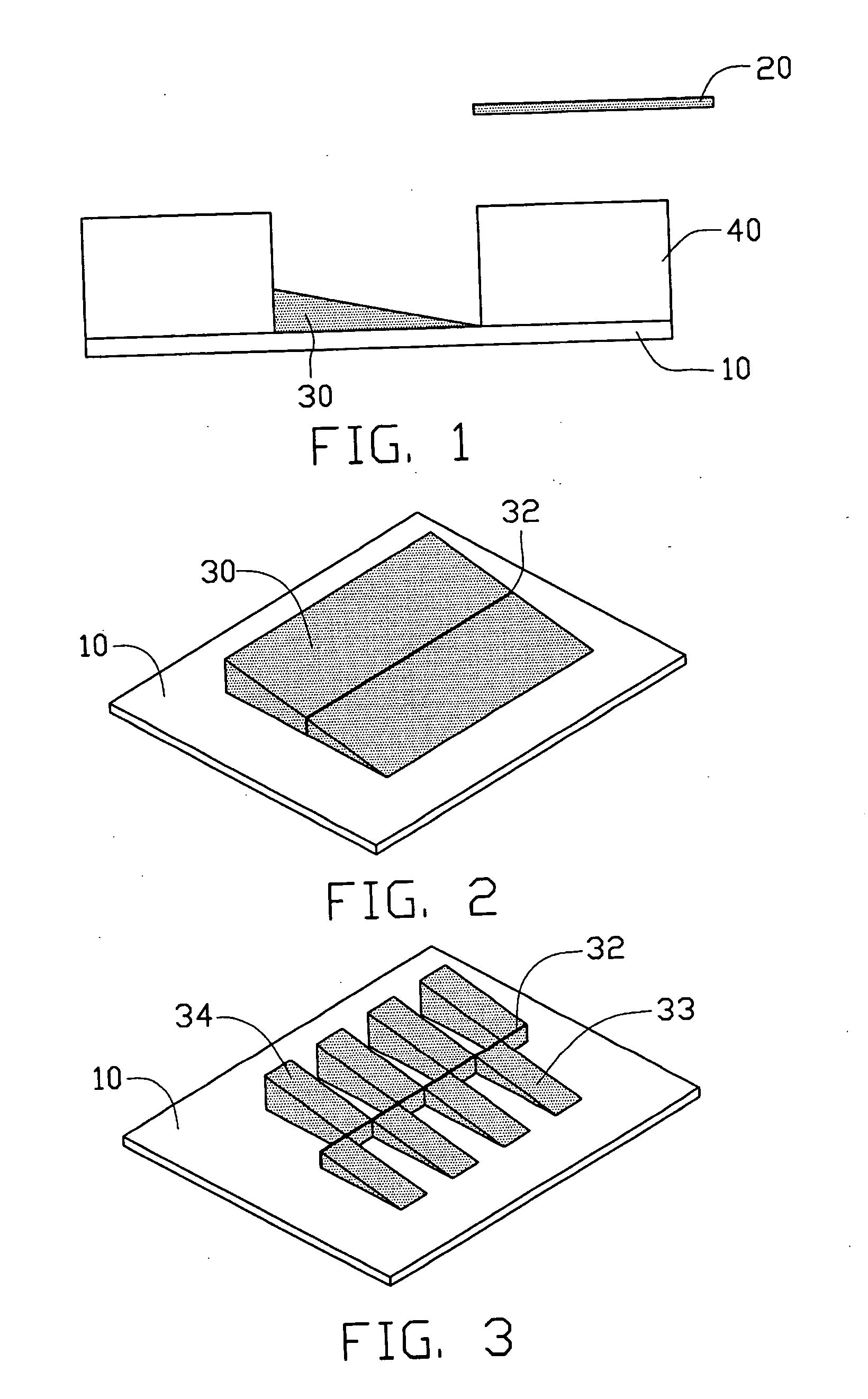
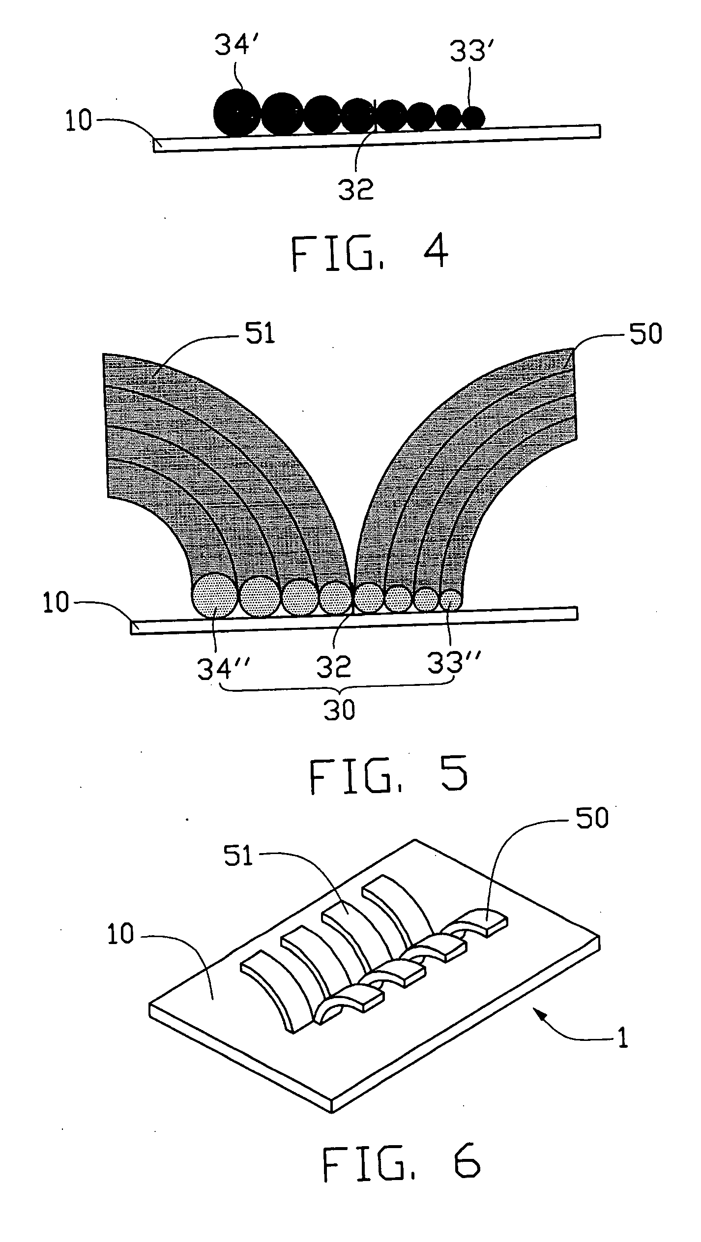
[0028] Referring to FIGS. 3 to 6, a preferred carbon nanotube-based device 1 according to the present invention includes a substrate 10, a catalyst layer 30 formed on the substrate 10, and a plurality of carbon nanotube arrays 50, 51 extending from the catalyst layer 30. The substrate 10 is generally made of a material selected from silicon, glass, or metal. The catalyst layer 30 includes material selected from the group consisting of iron, cobalt, nickel, and any suitable alloy thereof. The catalyst layer 30 includes a plurality of catalyst blocks 33, 34. A thickness of each of the catalyst blocks 33, 34 are gradually increases from a first end thereof to an opposite second end thereof. The catalyst blocks 33, 34 each have a region 32 with a thickness approximately equal to an optimum thickness for growing carbon nanotubes. The carbon nanotube arrays 50, 51 are arc-shaped, and bend in respective directions deviating from the region of optimum thickness 32. The carbon nanotubes in t...

second embodiment

[0029] Referring to FIGS. 10 to 14, a carbon nanotube-based device 2 according to the present invention includes a substrate 70, a catalyst layer 90 formed on the substrate 70, and a plurality of carbon nanotubes arrays 100, 101, 102, 103 extending from the catalyst layer 90. The catalyst layer 90 includes a plurality of catalyst blocks 93, 94, 95, 96. A thickness of each of the catalyst blocks 93, 94, 95, 96 gradually increases from a first end thereof to an opposite second end thereof. The catalyst blocks 93, 94, 95, 96 each have a region 92 with a thickness approximately equal to an optimum thickness for growing carbon nanotubes. The carbon nanotube arrays 100, 101, 102, 103 are arc shaped, and bend in respective directions deviating from the region of optimum thickness 92. The carbon nanotubes in the arrays 100, 101, 102,103 are bundled with each other.

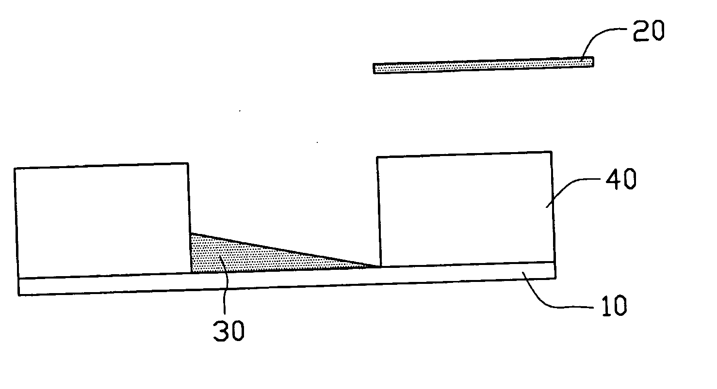
[0030] A preferred method for making the carbon nanotube-based device 1 will be described below with reference to FIGS. 1 to 6. ...


PUM

PropertyMeasurementUnit
thicknessaaaaaaaaaa
thicknessaaaaaaaaaa
diametersaaaaaaaaaa

Abstract

A preferred carbon nanotube-based device (1) includes a substrate (10), a catalyst layer (30) disposed on the substrate, and a plurality carbon nanotube arrays (50, 51) extending from the catalyst layer. The catalyst layer includes a plurality of catalyst blocks (33, 34), a thickness of the catalyst block is varied gradually from a first end thereof to an opposite second end thereof, and the catalyst block having a region with a thickness approximate to an optimum thickness for growing carbon nanotubes. The carbon nanotube arrays are arc-shaped, and bend in respective directions deviating from the region of optimum thickness. A preferred method for making the carbon nanotube-based device is also provided.

Description

BACKGROUND OF THE INVENTION [0001] 1. Field of the Invention [0002] The present invention relates to carbon nanotube-based devices and methods for making such carbon nanotube-based devices. [0003] 2. Description of the Related Art [0004] Carbon nanotubes are very small tube-shaped structures essentially having the composition of a graphite sheet rolled into a tube. Carbon nanotubes produced by arc discharge between graphite rods were first discovered and reported in an article by Sumio Iijima entitled “Helical Microtubules of Graphitic Carbon” (Nature, Vol. 354, Nov. 7, 1991, pp. 56-58). Carbon nanotubes have very good electrical conductance due to their structure. They are also chemically stable, and have very small diameters (less than 100 nanometers) and large aspect ratios (length / diameter). Due to these and other properties, it has been suggested that carbon nanotubes can play an important role in fields such as microscopic electronics, materials science, biology and chemistry....

Claims


Application Information

Patent Timeline
Patent Type & Authority Applications(United States)
IPC IPC(8): B32B9/00B32B17/06B32B15/04
CPCB82Y30/00B82Y40/00C01B31/0233Y10T428/30Y10S977/742Y10S977/843C01B2202/08C01B32/162
Inventor LIU, LIANGFAN, SHOU-SHAN
Owner TSINGHUA UNIV
Why Eureka
Try Eureka