Calibrating imaging devices

a technology for imaging devices and calibration tools, applied in the field of medical imaging, can solve the problems of increasing the complexity and time required for calibration, introducing potential errors, and unable to acquire sufficient independent images to use for calibration, etc., to achieve a more rapid and simplified calibration process for imaging devices, improve calibration tools, and facilitate the effect of a simplified calibration process

Active Publication Date: 2006-02-16
ELEKTA AB
View PDF69 Cites 42 Cited by
  • Summary
  • Abstract
  • Description
  • Claims
  • Application Information

AI Technical Summary

Benefits of technology

[0007] The present invention provides methods, apparatus and systems that facilitate a more rapid and simplified calibration process for imaging devices. More specifically, the process for calibrating hand-held ultrasound probes to a coordinate system of other imaging and/or treatment devices within a room is greatly simplified through improved calibration tools and the application of mathematical transforms to relate otherwise independent reference systems to each other. Using the methods and apparatus described below, technicians can quickly calibrate an imaging device using images from virtually any angle with respect to a calibration device, an

Problems solved by technology

However, wires can only be detected with ultrasound from very specific angles, making it difficult to acquire sufficient independent images to u

Method used


Image

  • Calibrating imaging devices
  • Calibrating imaging devices
  • Calibrating imaging devices

Examples


Embodiment Construction

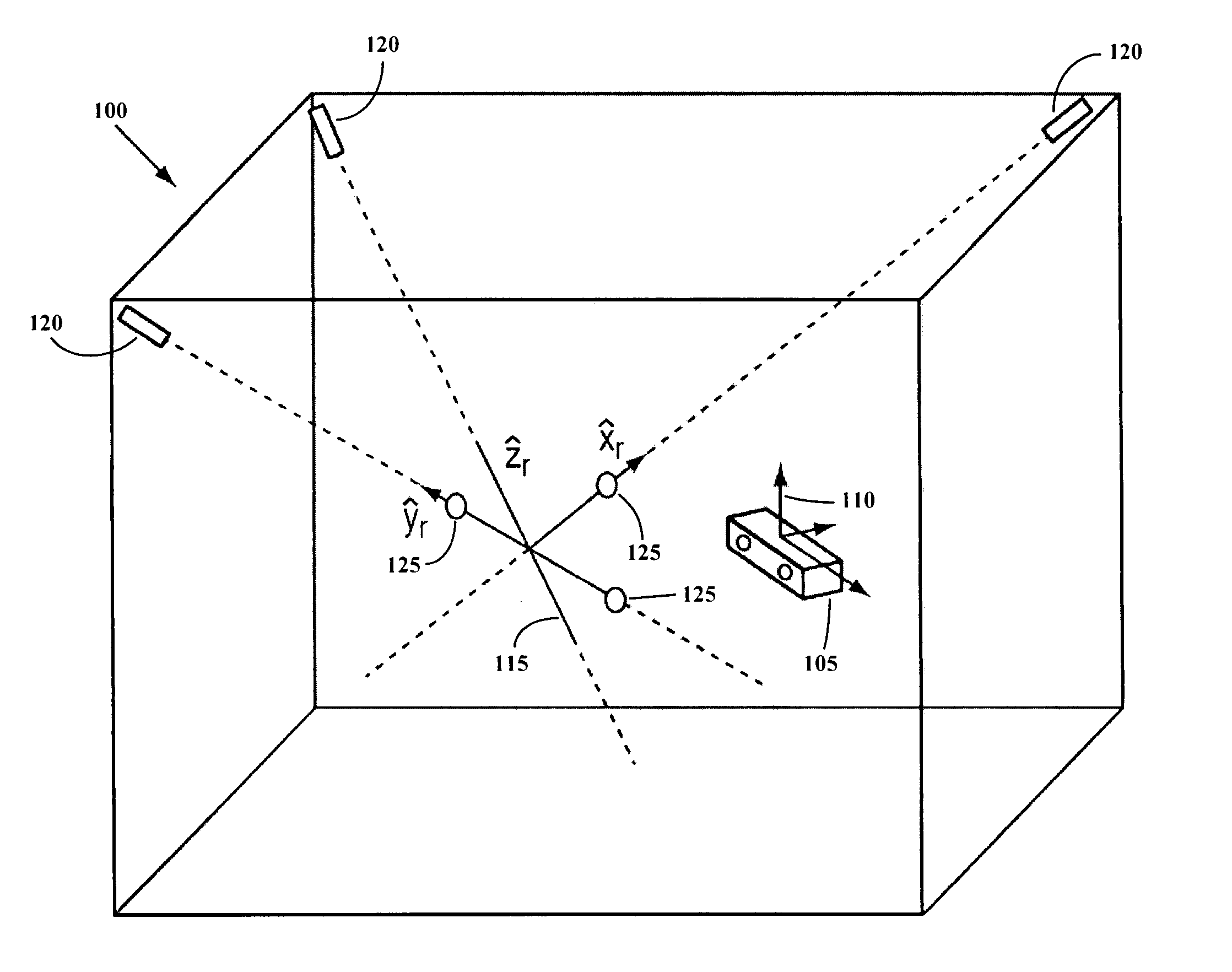
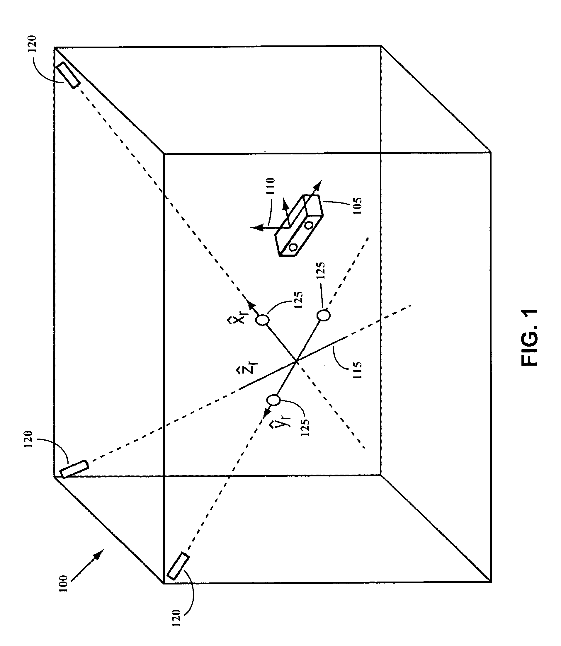
[0034] Throughout the following descriptions and example, the illustrative descriptions of the invention is described in the context of calibrating a hand-held ultrasound imaging probe to a three-dimensional reference coordinate system defined in a radiation treatment room. However, it is to be understood that the present invention may be applied to calibrating the location of virtually any hand-held imaging device to any reference coordinate system.

[0035] Radiation-emitting devices are used for the treatment of cancerous tumors within patients. The primary goal of radiation therapy is the complete eradication of the cancerous cells, while the secondary goal is to avoid, to the maximum possible extent, damaging healthy tissue and organs in the vicinity of the tumor. Typically, a radiation therapy device includes a particle linear accelerator (“LINAC”) that generates a high-energy radiation beam of therapy, such as an electron beam or photon (x-ray) beam. The patient is placed on a ...


PUM


Abstract

Methods and apparatus for calibrating images and imaging devices to common coordinate systems utilize, in some embodiments, rods that detectably reflect an acoustic signal regardless of the incidence angle of the signal with respect to the rods. Typically, the rods are disposed within a “phantom” at known positions with respect to a room coordinate system. Images of the cylindrical rods may be obtained from different directions, allowing the imaging device to be calibrated to the room coordinate system.

Description

CROSS-REFERENCE TO RELATED APPLICATIONS [0001] This application claims priority to U.S. provisional patent application Ser. No. 60 / 589,432, filed Jul. 20, 2004, and U.S. provisional patent application Ser. No. 60 / 590,823, filed Jul. 23, 2004.FIELD OF THE INVENTION [0002] The invention relates generally to the field of medical imaging, and, in particular, to calibrating medical imaging devices to reference coordinate systems. BACKGROUND INFORMATION [0003] Hand-held two-dimensional ultrasound devices are used to create diagnostic images of anatomical features of a patient. Because many of the images are further used to plan and administer treatment to organs, lesions, and other anatomical structures, the accuracy of the images is critical. One aspect of an image's accuracy is the degree to which the structures in the image can be placed at identifiable locations in space relative to a set of fixed markers or a known reference coordinate system. [0004] One approach is to calibrate the ...

Claims


Application Information

Patent Timeline
IPC IPC(8): A61B8/00
CPCA61B8/00A61B8/4245G01S15/8936A61B2019/5289G01S7/5205A61B8/587A61B8/4209A61B2090/364
Inventor LACHAINE, MARTINFALCO, TONYAUDET, VERONIQUEHUANG, XING
Owner ELEKTA AB
Why Eureka
Try Eureka