
General drive control system and generat drive control method

a technology of general drive control and generat drive, applied in the direction of propulsion parts, process and machine control, propulsion using engine-driven generators, etc., can solve the problems of limited energy that can be consumed by the machine, and difficult to achieve the target state of operation, etc., to achieve the effect of saving energy consumption, saving energy consumption, and facilitating relation adjustmen

Inactive Publication Date: 2006-02-16
TOYOTA JIDOSHA KK
View PDF6 Cites 51 Cited by
  • Summary
  • Abstract
  • Description
  • Claims
  • Application Information

AI Technical Summary

Benefits of technology

[0011] In the present system, in view of the power or work of each of the plurality of actuators, drive of the plurality of actuators is generally controlled. Here, a relation holds between the power or work of each actuator and energy consumption that the smaller the power or work, the smaller the energy consumption.
[0115] According to this method, when the “machine” of aspect (22) is a moving body used by a human being, it becomes easier to appropriately distribute available power or available work, which is the power or work that can be supplied by the energy source to the plurality of actuators as a whole, considering safety of the moving body, comfort of the moving body when the human being uses the moving body, and economy of energy consumption by the plurality of actuators.

Problems solved by technology

In any case, the energy that can be consumed by the machine is limited in today's world where resources and energy must be saved.
In that case, it is not an easy task to realize target state of operation and to save energy consumption simultaneously.
This approach, however, is not practical from the economical viewpoint and from physical viewpoint such as weight and size.
Even when the prior art technique is implemented, the amount of energy consumed by the plurality of actuators when they are driven together can not be taken into consideration.
Therefore, it is not possible by the prior art technique to optimize drive of the plurality of actuators from the viewpoint of saving energy consumption.

Method used


Image

  • General drive control system and generat drive control method
  • General drive control system and generat drive control method
  • General drive control system and generat drive control method

Examples


Embodiment Construction

[0138] In the following, some specific embodiments of the present invention will be described in detail with reference to the figures.

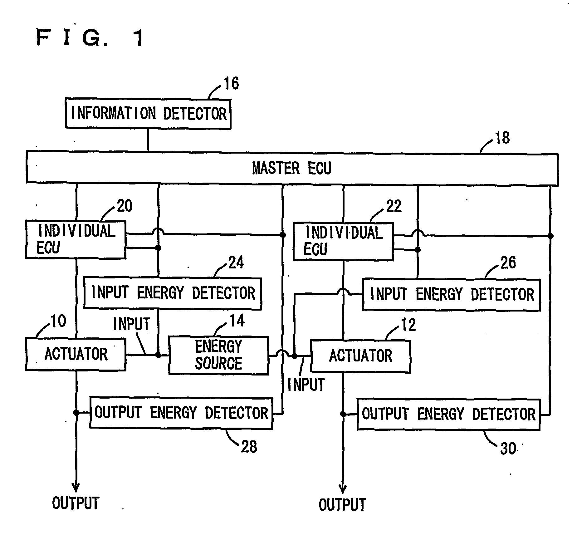
[0139]FIG. 1 is a block diagram of a hardware configuration of the general drive control system in accordance with the first embodiment of the present invention. The general drive control system is mounted on a motor vehicle (hereinafter also referred to as a vehicle) as a machine. The motor vehicle includes a plurality of actuators (in FIG. 1, represented by two actuators) 10, 12, and an energy source 14 common to these actuators.

[0140] The general drive control system includes driving information detector 16 detecting driving information, and a master ECU (Electronic Control Unit) 18. Further, the general drive control system includes, for respective actuators 10, 12, individual ECUs 20, 22, input energy detectors 24, 26 and output energy detectors 28, 30.

[0141] Driving information detector 16 is provided to detect a driver's instruction issued b...


PUM


Abstract

In a vehicle including a plurality of actuators and an energy source common to the actuators and accomplishing work by an operation of the plurality of actuators consuming energy supplied from the energy source, drive of the plurality of actuators is optimized from the viewpoint of saving energy consumed by the plurality of actuators. The general driving method includes the steps of determining, for each actuator, power to meet driving request as a desired power DMP, determining electric power to be supplied to each actuator to realize the desired power as required electric power REP, and when total required electric power REPsum as a sum of required electric powers determined for the plurality of actuators exceeds an allowable power AMP, decreasing, for some of the actuators, the corresponding desired power to establish the desired power for each of the plurality of actuators.

Description

TECHNICAL FIELD [0001] The present invention relates to a technique for controlling, in a machine including a plurality of actuators and an energy source common to the actuators, drive of the plurality of actuators. More specifically, the present invention relates to a technique for optimizing drive of the plurality of actuators from the viewpoint of saving energy consumed by the plurality of actuators. BACKGROUND ART [0002] In a machine for work, energy is consumed to accomplish the work. The energy necessary therefor may be supplied externally, or the machine itself may have an energy source and supply the energy by itself. [0003] In any case, the energy that can be consumed by the machine is limited in today's world where resources and energy must be saved. Therefore, it is strongly desired to realize target state of operation and to save consumed energy simultaneously in one same machine. [0004] There may be a case where the machine has a plurality of actuators and the actuators...

Claims


Application Information

Patent Timeline
Patent Type & Authority Applications(United States)
IPC IPC(8): G06F17/00B60W10/00B60H1/00B60L7/10B60L11/18B60L15/20B60L50/16B60W10/04B60W10/06B60W10/08B60W10/10B60W10/18B60W10/184B60W10/20B60W10/26F16H61/662
CPCB60K1/02B60K6/48B60L7/10B60L2270/44B60L2200/26F16H61/662Y02T10/6221Y02T10/7258B60W10/26Y02T10/62Y02T10/72B60W30/184B60W50/00
Inventor ISONO, HIROSHIMIZUTANI, YASUJIYAMAMOTO, TAKAYUKITAKEUCHI, KOICHI
Owner TOYOTA JIDOSHA KK
Learn More