Gas turbine combustion chamber

Inactive Publication Date: 2006-02-23
SIEMENS AG
View PDF3 Cites 5 Cited by
  • Summary
  • Abstract
  • Description
  • Claims
  • Application Information

AI Technical Summary

Benefits of technology

[0013] The advantage of the invention lies particularly in the fact that the manhole cover withstands a high level of thermal loading as a result of an inner cooling chamber, with extremely simple removal of the manhole cover, including its inner cooling chamber, being enabled by the manhole.
lies particularly in the fact that the manhole cover withstands a high level of thermal loading as a result of an inner cooling chamber, with extremely simple removal of the manhole cover, including its inner cooling chamber, being enabled by the manhole.

Problems solved by technology

However a manhole in the combustion chamber is frequently dispensed with, particularly in gas turbines with high combustion temperatures of 1200° C. to 1300° C., since it would not withstand the thermal loading prevalent therein, or could not guarantee at least the leak-tightness of the combustion chamber.
Extremely costly de-installation work is necessary in order to allow a person entry into the combustion chamber.

Method used


Image

  • Gas turbine combustion chamber
  • Gas turbine combustion chamber
  • Gas turbine combustion chamber

Examples


Embodiment Construction

[0017] Identical parts are provided with the same reference characters in both figures.

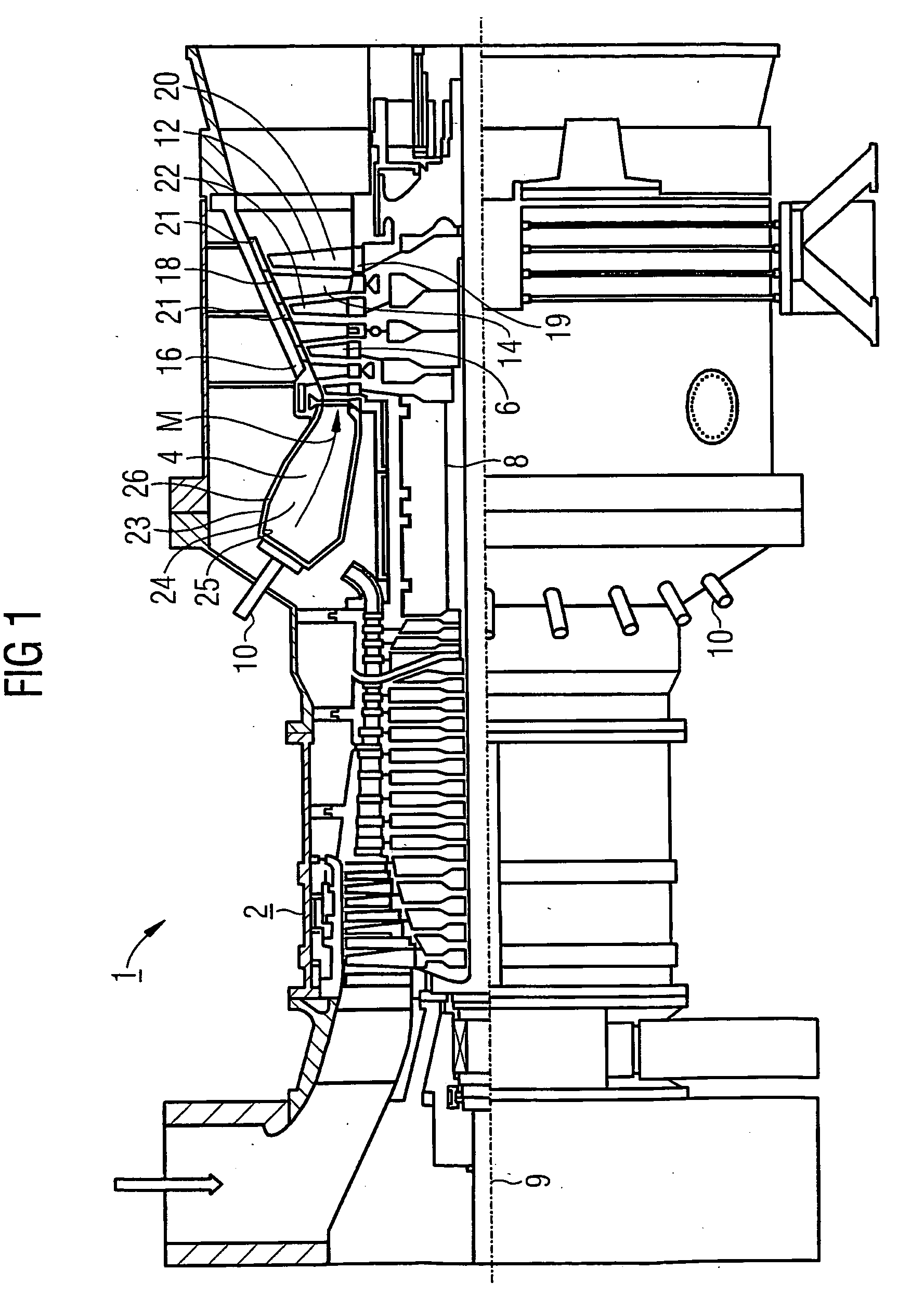
[0018] The gas turbine 1 according to FIG. 1 has a compressor 2 for combustion air, a combustion chamber or a gas turbine combustion chamber 4 and a turbine 6 for driving the compressor 2 and a generator (not shown) or a machine. To this end, the turbine 6 and the compressor 2 are arranged on a common turbine shaft 8 known as a turbine rotor, to which the generator and / or the machine are also connected, and which is supported such that it can be rotated about its center axis 9.

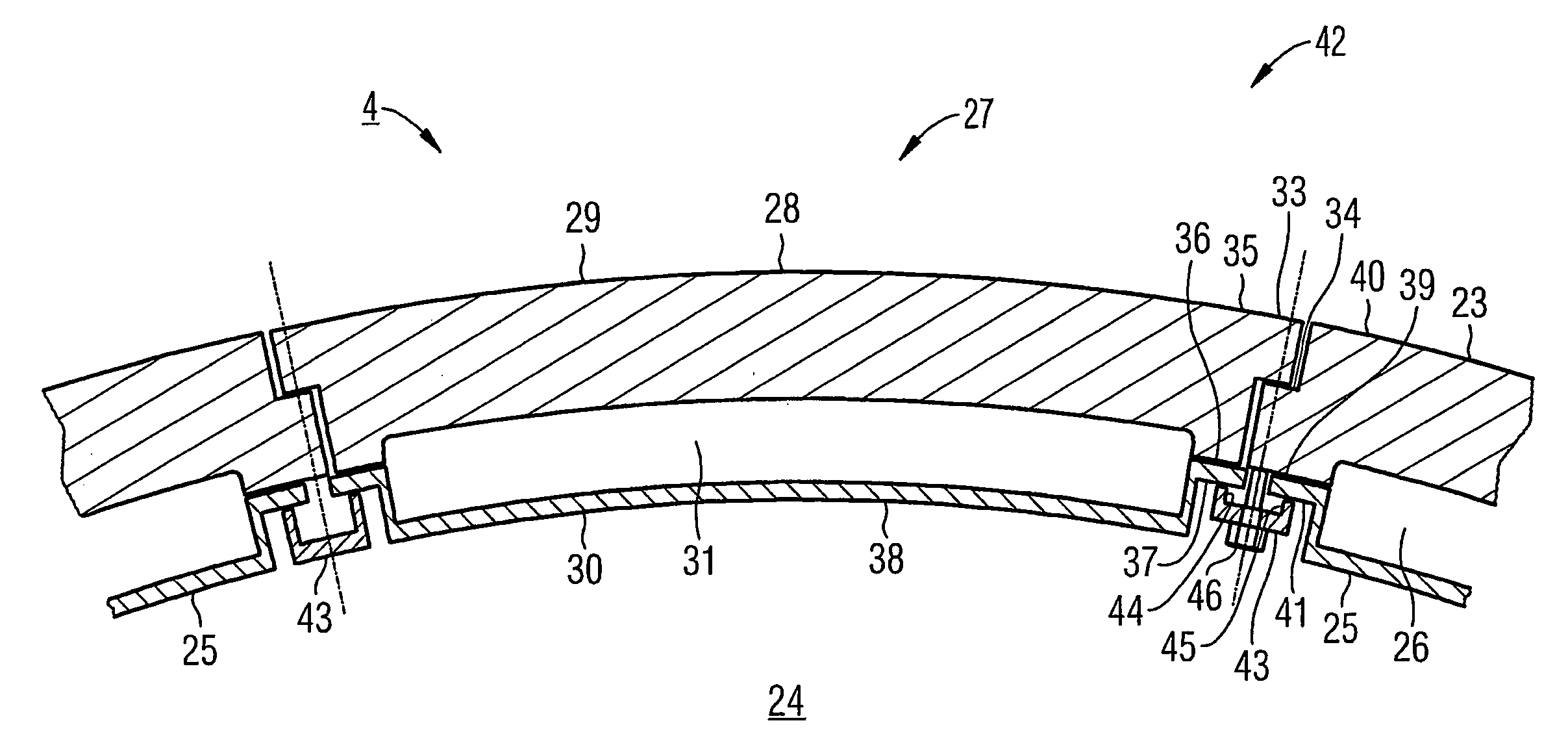
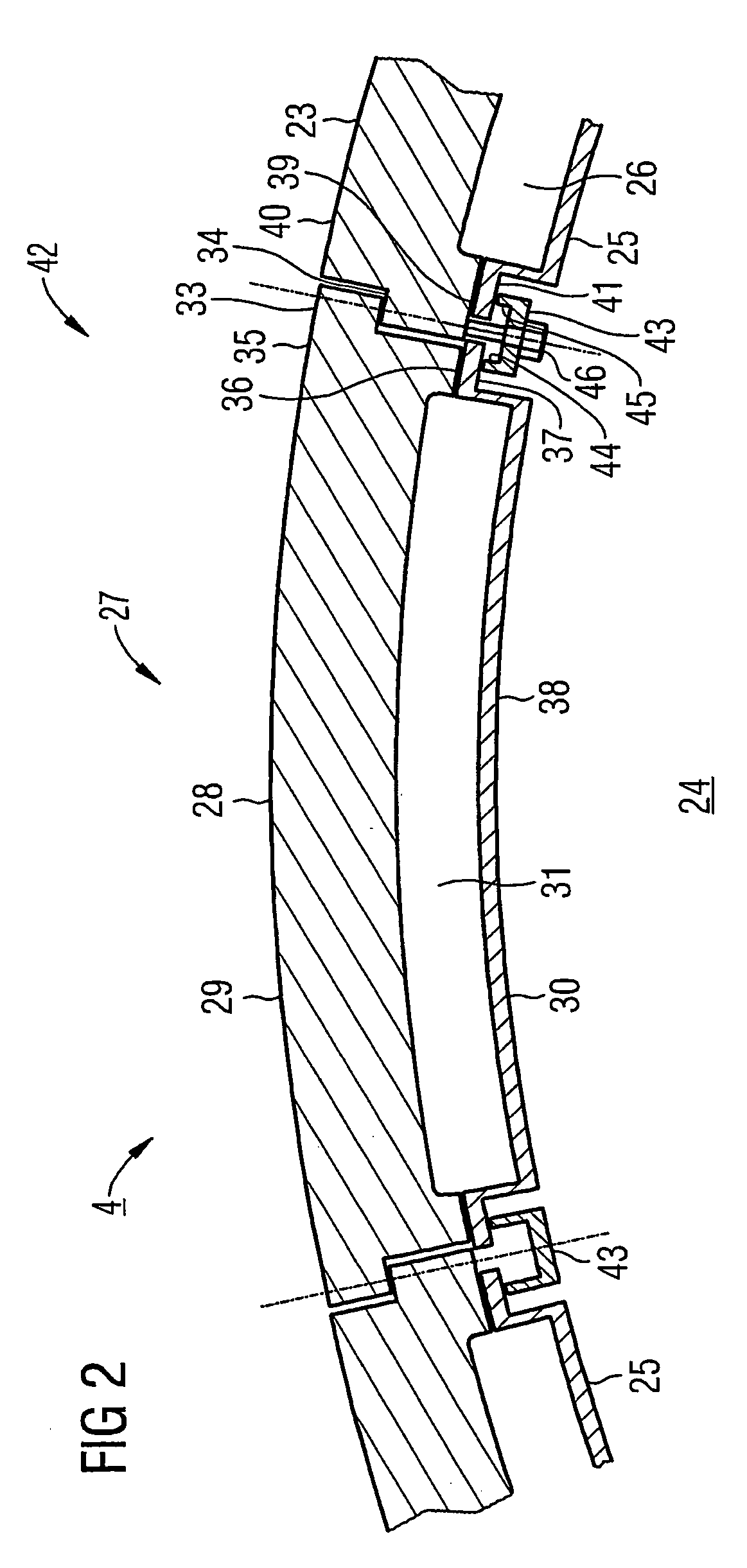
[0019] The combustion chamber 4 is equipped with a number of burners 10 for combusting a liquid or a gaseous fuel. Furthermore liner elements 25 are provided on its interior wall or combustion chamber wall 23.

[0020] The turbine 6 comprises a number of rotatable blades 12 connected to the turbine shaft 8. The blades 12 are arranged in a ring shape on the turbine shaft 8, thus forming a number of rows of blades. The turbine...


PUM


Abstract

A gas turbine combustion chamber comprises a manhole as access to a combustion chamber interior, which may be sealed with a manhole cover. The manhole comprises an inner cooling chamber and may thus take particularly high thermal loads.

Description

CROSS REFERENCE TO RELATED APPLICATION [0001] This application is the U.S. National Stage of International Application No. PCT / EP2003 / 008548, filed Aug. 1, 2003 and claims the benefit thereof. The International Application claims the benefits of European Patent application No. 02018489.1 EP filed Aug. 16, 2002, both of the applications are incorporated by reference herein in their entirety.FIELD OF THE INVENTION [0002] The invention relates to a gas turbine combustion chamber with a manhole as access to a combustion chamber interior, which may be sealed with a manhole cover. BACKGROUND OF THE INVENTION [0003] Gas turbines are used in many fields for driving generators or machines. The energy content of a fuel is thereby used to generate a rotational movement of a turbine shaft. For this purpose, the fuel is combusted in a combustion chamber, with compressed air being supplied by an air compressor. The operating medium which is generated in the combustion chamber by fuel combustion, ...

Claims


Application Information

Patent Timeline
IPC IPC(8): F23R3/42F02C7/00F02C7/18F23M7/04F23R3/00
CPCF23R3/005F23M7/04
Inventor TIEMANN, PETEROLTMANNS, IRIS
Owner SIEMENS AG
Why Eureka
Try Eureka