Data transmission method and data trasmission system

a data transmission and data transmission technology, applied in the field of data transmission methods and data transmission systems, can solve the problems of high transmission cost, low quality of service, and often uncompensated bands, and achieve the effect of reducing the traffic of signals flowing over the entire network

Inactive Publication Date: 2006-02-23
TAKASHIMA MASATOSHI +4
View PDF2 Cites 44 Cited by
  • Summary
  • Abstract
  • Description
  • Claims
  • Application Information

AI Technical Summary

Benefits of technology

[0108] An object of the present invention is to provide a data transmission method and a data transmission system capable of reducing traffic of signals flowing over the entire network.
[0109] A second object of the present invention is to provide a data transmission method and a data transmission system not requiring a large delay unit in the MCU performing the multiplexing and composition and therefore capable of reducing the hardware size.
[0110] A third object of the present invention is to provide a data transmission method and a data transmission system achieving an improvement of a utilization efficiency of the transmission bands and a reduction of the transmission cost.

Problems solved by technology

In the Internet, the band is often not compensated.
Therefore, it is an area where the quality of service (QoS) is low.
These signals are transmitted over bands having the same QoS, so the transmission cost becomes high.
Further, from the viewpoint of effective utilization of the bands, the utilization efficiency was low.
In the case of audio and video, this will result in lip-sync deviation and an extremely strange feeling.
When communicating by utilizing only a network having a low QoS, there is a possibility of large jitters or large delay occurring in accordance with the state of congestion of the network.
Further, if a large delay is inserted, in the communication, a deviation occurs in the responses to each other and conversation ends up becoming impossible.
Further, if a state of congestion occurs in the network, the audio will be interrupted.
Not only it is then difficult to use this system as a communication tool, but also there is the problem that once congestion occurs, the system cannot be restored for a long time.

Method used


Image

  • Data transmission method and data trasmission system
  • Data transmission method and data trasmission system
  • Data transmission method and data trasmission system

Examples


first embodiment

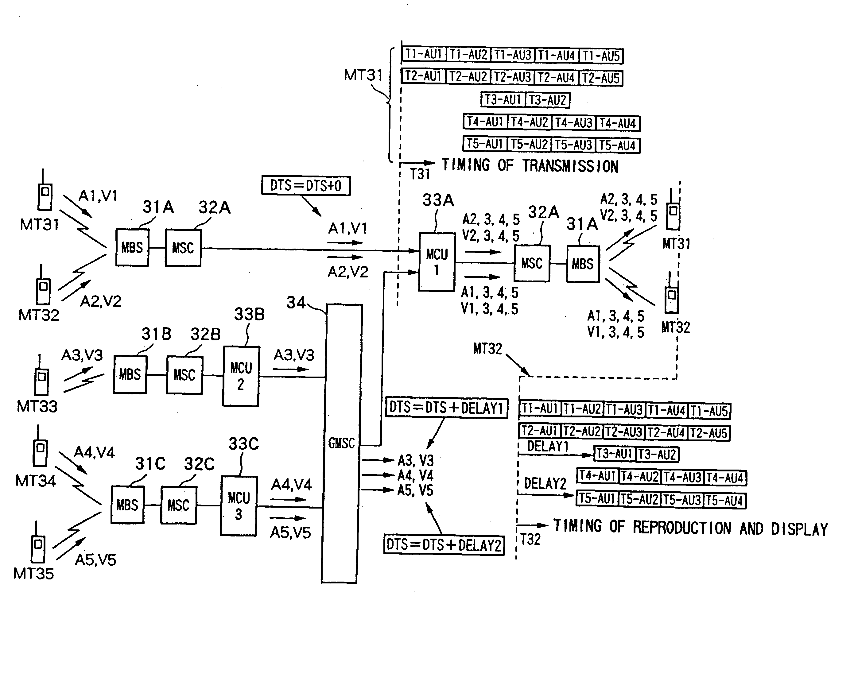
[0165]FIG. 11 and FIG. 12 are views for explaining a first embodiment of a data transmission system employing a data transmission method according to the present invention. FIG. 11 shows a signal transmission state in a case of multipoint communication, while FIG. 12 shows a state where the signals in the case of multipoint communication are reproduced and displayed at the terminals.

[0166] A data transmission system 30 according to the first embodiment is configured based on the following characteristics.

[0167] 1) The signals transmitted from multiple points are deliberately shifted for reproduction and display in accordance with the transmission delays instead of matching the phases of the data (signals) input to the terminals at the same time.

[0168] 2) In order to realize 1), when transmitting the same access units to a plurality of MCUs (multipoint control devices), different delay values are added to the DTS (decoding time stamp) in accordance with the transmission delays and...

second embodiment

[0195]FIGS. 13A to 13 E, FIGS. 14A and 14B, and FIGS. 15A and 15B are views for explaining a second embodiment of a data transmission system employing a data transmission method according to the present invention.

[0196] A data transmission system 30A according to the second embodiment is configured based on the following characteristics.

[0197] 1) When combining and transmitting a plurality of signals, only the information concerning the audio is added at the baseband (PCM) to obtain a signal of one channel. The video is transmitted by bundling a plurality of channels while keeping the packet form.

[0198] 2) When transferring the data required for the multiplexing among the MCUs, by sending the signals as in 1) to each other, the amount of information of the signals flowing among the MCUs is reduced.

[0199] 3) When transmitting the multiplexed signals from the MCU to the terminals, by transmitting the signals multiplexed as in 1), the amount of the information flowing through the t...

third embodiment

[0220]FIG. 16, FIG. 17, and FIG. 18 are views for explaining a third embodiment of a data transmission system employing a data transmission method according to the present invention.

[0221] The data transmission system according to the third embodiment is configured based on the following characteristics.

[0222] The signals where continuity is regarded as important (for example the information concerning the audio) are transmitted over a network having a higher QoS (quality of service), while the signals for which discontinuity can be permitted (for example the video) are transmitted over a network having a lower QoS.

[0223] A network having a high QoS includes a circuit switched network at present, while a network having a low QoS includes a packet switching network.

[0224] Therefore, in the third embodiment, the information concerning the audio is transmitted to the circuit switched network, and the information concerning the video is transmitted to the packet switching network.

[...


PUM


Abstract

A data transmission method and a data transmission system not requiring a large delay unit for multiplexing and composition and capable of reducing the hardware scale, wherein when transmitting data among multiple points from a plurality of terminals arranged in a network, when the data at multiple points are transmitted to the terminals, in the network, identical packets are added different time stamps in accordance with the transmission delays, whereby the data shifted in accordance with the transmission delays are transmitted.

Description

RELATED APPLICATION DATA [0001] The present application claims priority to Japanese Application No. P2000-081851 filed Mar. 17, 2000, which application is incorporated herein by reference to the extent permitted by law. BACKGROUND OF THE INVENTION [0002] The present invention relates to a data transmission method and a data transmission system for transmitting a plurality of streams over a network when communicating, streaming, etc. among a plurality of terminals. [0003] Below, an explanation will be made of a conventional method for transmitting a plurality of streams over a network when communicating, streaming, etc. among a plurality of terminals in relation to the drawings. [0004]FIG. 1 is a view of an example of a television (TV) conference system. [0005] In this TV conference system, a conference is simultaneously carried out by using five terminals of a terminal 1 to a terminal 5 with cameras CMR mounted thereon. [0006] The terminals 1 to 5 are connected via switches SW1 to S...

Claims


Application Information

Patent Timeline
Patent Type & Authority Applications(United States)
IPC IPC(8): H04N7/14H03M7/30H04J3/00H04L12/18H04L29/00H04N7/15H04N21/6437
CPCH04N7/152H04N21/4347H04N21/2365H04N21/2187H04N21/23608H04N21/2665H04L65/765H04L65/70
Inventor TAKASHIMA, MASATOSHINARITA, HIDEYUKIMURAYAMA, HARUYOSHIITO, YOSHIYUKIHIRANAKA, DAISUKE
Owner TAKASHIMA MASATOSHI
Why Eureka
Try Eureka