
Multi-channel, multi-spectrum imaging spectrometer

a multi-spectrum imaging and spectrometer technology, applied in the field of compact, multi-channel and/or multi-spectrum imaging concentric spectrometers, can solve the problems of large size of conventional spectrometers used for raman analysis, heavy laboratory-based instruments, and the inability to produce spectra of relatively limited wavelength ranges

Active Publication Date: 2006-02-23
HEADWALL PHOTONICS
View PDF20 Cites 114 Cited by
  • Summary
  • Abstract
  • Description
  • Claims
  • Application Information

AI Technical Summary

Benefits of technology

[0009] A prism, a set of mirrors or another optical element(s) folds the input channel(s) of a spectrometer to enable the inputs to be moved away from the plane of the image sensor, thereby enabling a large camera or other device to be attached to the spectrometer, without blocking the input(s) in a retroflective configuration.
[0010] A mounting mechanism enables a curved optical element to be adjusted within a spectrometer or other instrument, without requiring a gimbal mount. The mounting mechanism enables the optical element to be moved laterally and transversely. For small excursions about a central location, such linear movements closely approximate the two angular degrees of freedom provided by a pair of gimbals for an incident beam.

Problems solved by technology

Conventional spectrometers used for Raman analysis are relatively large and heavy laboratory-based instruments, primarily due to the large optical focal lengths inherent in the designs of high resolution instruments.
In addition, conventional spectrometers can produce spectra of fairly limited ranges of wavelengths at higher reciprocal dispersions.

Method used


Image

  • Multi-channel, multi-spectrum imaging spectrometer
  • Multi-channel, multi-spectrum imaging spectrometer
  • Multi-channel, multi-spectrum imaging spectrometer

Examples


Embodiment Construction

[0036] The contents of U.S. Provisional Patent Application No. 60 / 602,747, filed Aug. 19, 2004, titled “Multi-Channel, Multi-Spectrum Imaging Spectrometer,” is hereby incorporated by reference.

[0037] For simplicity, visible light will be used to describe the operation of the prior art and the present invention. However, the present invention can be used with visible light and invisible light, such as near-infrared (NIR), short wave infrared (SWIR) and ultraviolet (UV) light, as well as other wavelengths of electromagnetic energy and combinations of visible and invisible energy, all of which are herein collectively referred to as “light” for simplicity.

Conventional Spectrometers

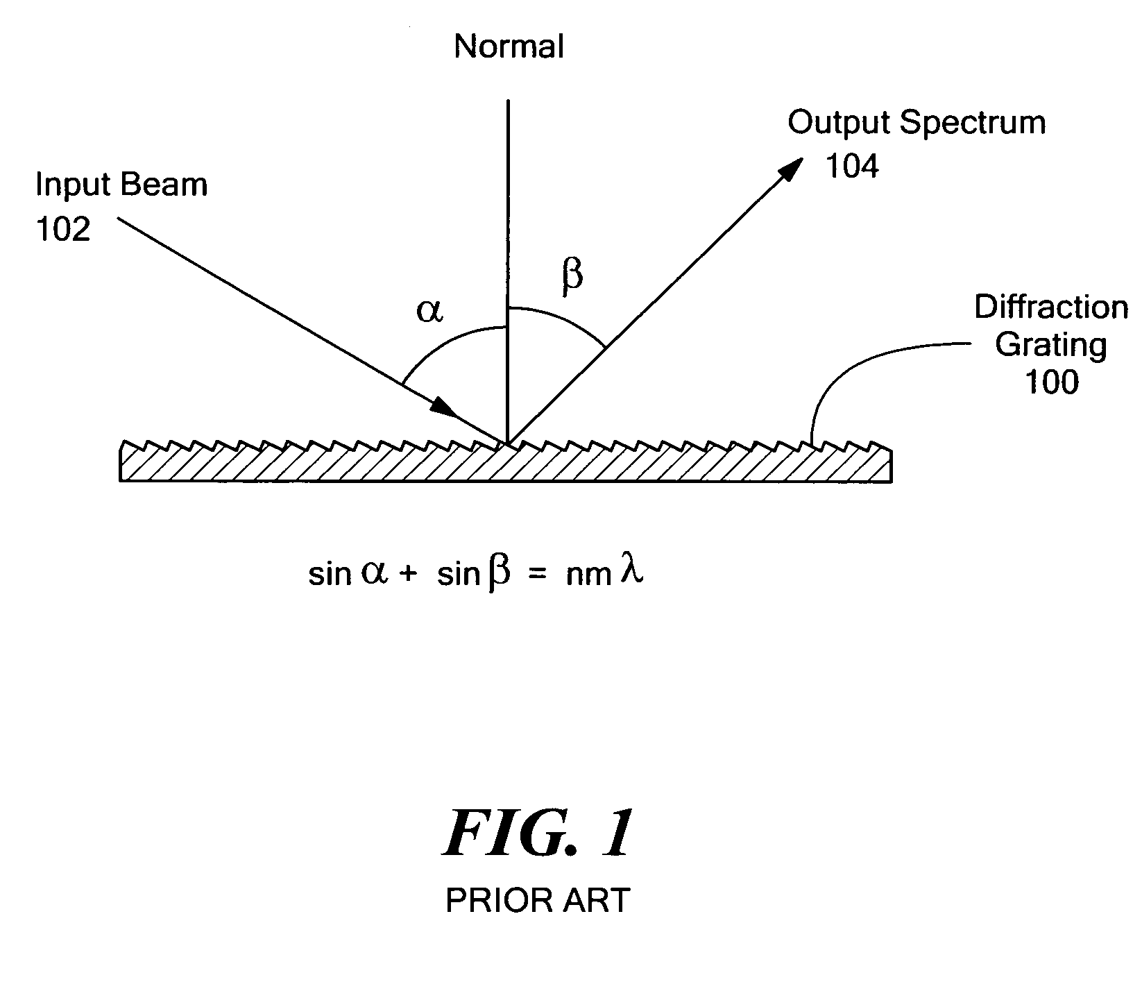
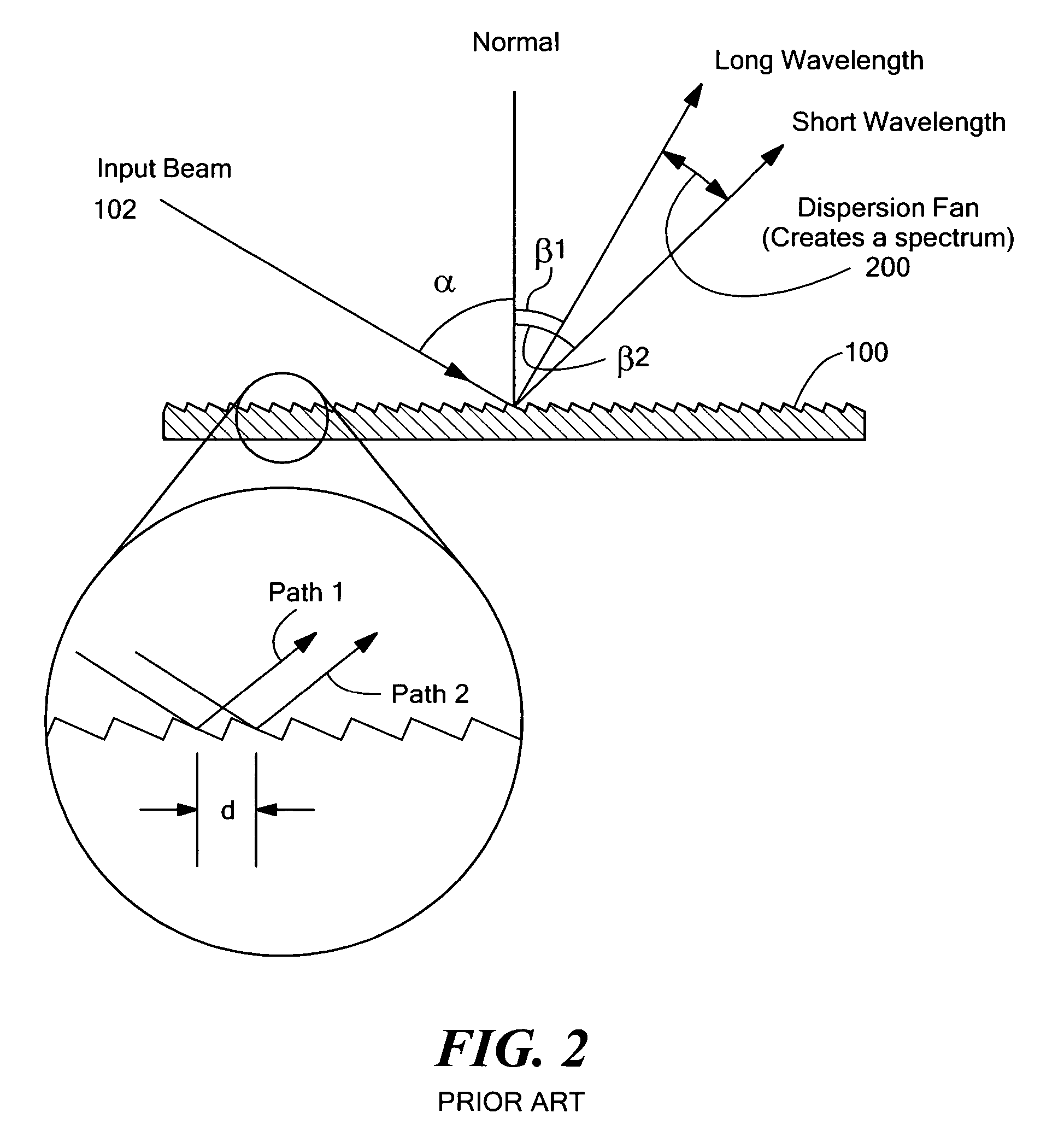
[0038] A typical spectrometer includes a slit or other light entry device, a light dispersing element for dispersing the incoming light into a spectrum, and an image plane, such as a screen or image sensor, on which the spectrum is projected. Most spectrometers use a diffraction grating as the light dispers...


PUM


Abstract

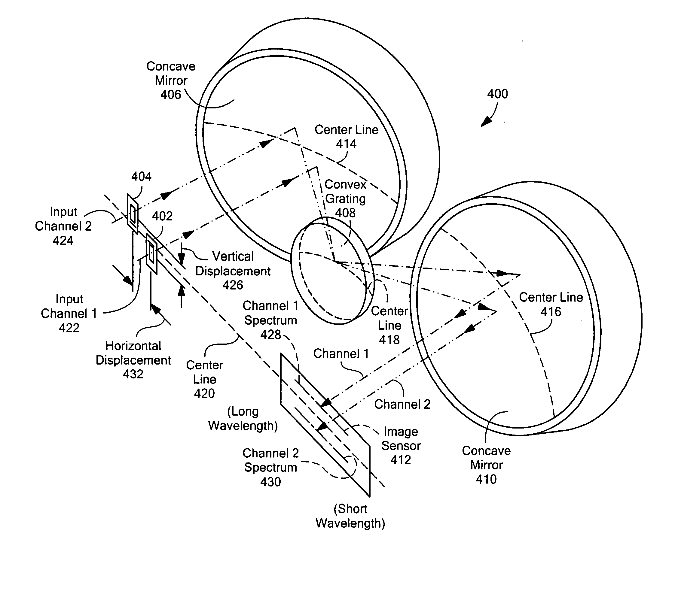
A multi-spectrum, multi-channel imaging spectrometer includes two or more input slits or other light input devices, one for each of two or more input channels. The input slits are vertically and horizontally displaced, with respect to each other. The vertical displacements cause spectra from the two channels to be vertically displaced, with respect to each other, on a single image sensor on a stationary image plane. The horizontal displacements cause incident light beams from the respective input channels to strike a convex grating at different respective incidence angles and produce separate spectra having different respective spectral ranges. A retroflective spectrometer includes a convex grating that, by diffraction, disperses wavelengths of light at different angles and orders approximately back along an incident light beam. A single concave mirror reflects both the input channel and the dispersed spectrum. A prism, set of mirrors, beam splitters or other optical element(s) folds the input channel(s) of a spectrometer to enable the input(s) to be moved away from the plane of the image sensor, thereby enabling a large camera or other device to be attached to the spectrometer without blocking the input(s). A mounting mechanism enables a curved optical element to be adjusted through lateral and transverse translations, without requiring a gimbal mount.

Description

CROSS REFERENCE TO RELATED APPLICATIONS [0001] This application claims the benefit of U.S. Provisional Patent Application No. 60 / 602,747, filed Aug. 19, 2004, titled “Multi-Channel, Multi-Spectrum Imaging Spectrometer.”STATEMENT REGARDING FEDERALLY SPONSORED RESEARCH OR DEVELOPMENT Not Applicable BACKGROUND OF THE INVENTION [0002] The present invention relates to imaging spectrometers and, more particularly, to compact, multi-channel and / or multi-spectrum imaging concentric spectrometers. [0003] A spectrometer is an instrument that separates radiation, such as light, into a spectrum of energy bands (wavelengths) and indicates the relative intensity of each band. In the case of visible light, a spectrometer typically separates the light into a spectrum that ranges from violet (short wavelength) light to red (long wavelength) light. [0004] Analyzing a spectrum of electromagnetic energy that is reflected from, or emitted by, an object can assist in identifying the chemical composition ...

Claims


Application Information

Patent Timeline
IPC IPC(8): G01J3/28
CPCG01J3/02G01J3/0202G01J3/0205G01J3/0208G01J3/021G01J3/0218G01J3/2823G01J3/0291G01J3/0294G01J3/0297G01J3/04G01J3/18G01J3/0237
Inventor JULIAN, JASON P.DIDONA, KEVIN M.MILNER, DARRIN P.MIKES, THOMAS L.MILLIGAN, SCOTT D.BANNON, DAVID P.
Owner HEADWALL PHOTONICS
Learn More