Efficient optical system and beam pathway design for laser-based distance measuring device

a laser-based distance measurement and optical system technology, applied in the direction of distance measurement, optical elements, instruments, etc., can solve the problems of large, expensive implementation system, limited flexibility in the use of more than one type of in-sight display technology, inconvenient manufacturing and assembly, etc., to achieve convenient manufacturing and assembly, low cost, and cost-effective

Active Publication Date: 2006-02-23
LASER TECH INC +1
View PDF27 Cites 10 Cited by
  • Summary
  • Abstract
  • Description
  • Claims
  • Application Information

AI Technical Summary

Benefits of technology

[0004] Disclosed herein is an optical system and beam transmission and reception pathway design of particular applicability in the implementation of a cost effective, compact laser-based range-finding instrument. The design is one in which the visual pathway may be made coincident with either the laser transmission or laser reception pathway and may conveniently be implemented in conjunction with a low cost liquid crystal display (LCD) aiming reticle and head up (HUD) information display or in conjunction with a light emitting diode (LED) element. In accordance with the present invention, relatively inexpensive plate mirrors may be used to replace more conventional and costly prism-based implementations.

Problems solved by technology

These comparatively complicated designs require the use of two or more relatively costly prisms along with as many as six or seven polished faces resulting in large, expensively implemented systems having little flexibility in the use of more than one type of in-sight display technologies.
While generally representative of the current state of the art in such designs, the afore-mentioned patents all describe systems of lenses and prisms which are relatively complex to implement, space inefficient, as well as costly to manufacture and assemble.

Method used


Image

  • Efficient optical system and beam pathway design for laser-based distance measuring device
  • Efficient optical system and beam pathway design for laser-based distance measuring device
  • Efficient optical system and beam pathway design for laser-based distance measuring device

Examples


Embodiment Construction

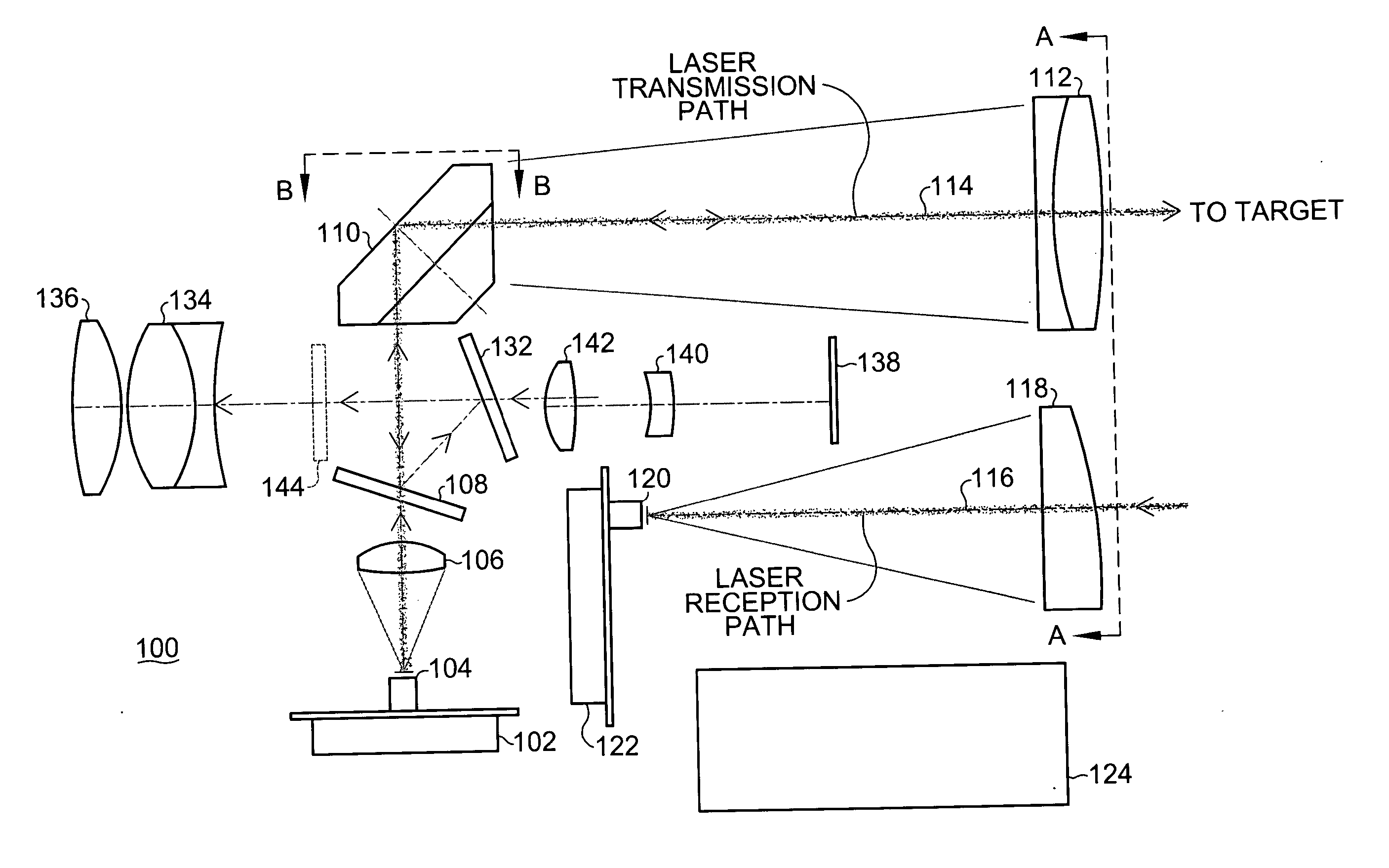
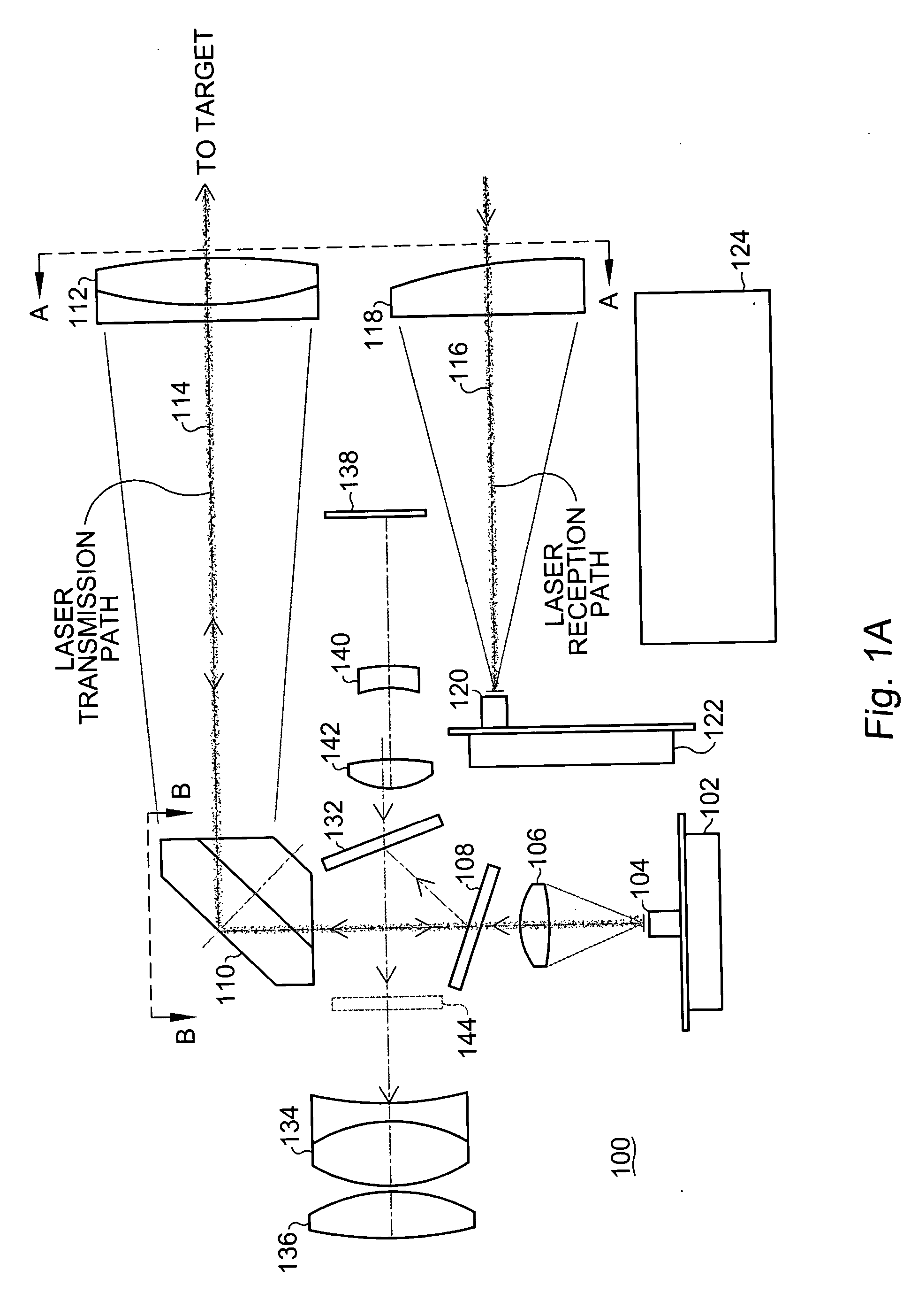
[0021] With reference now to FIG. 1A, a cost and space efficient optical system 100 and beam pathway design for a laser-based distance measuring device is shown with respect to the laser transmission and reception paths thereof in particular.

[0022] The system 100 comprises, in pertinent part, a laser transmission board including a laser light emitting element 104. The laser light emitting element 104 projects a pulsed infrared laser beam along a laser transmission path through a first lens 106 and an infrared dichroic mirror 108 to an Amici prism 110. The Amici prism 110, also sometimes referred to as a “roof prism” is a right angle prism in which the hypotenuse has been replaced by a roof wherein two flat faces meet at a 90° angle. The laser beam exits the Amici prism 110 towards the objective lens 112. Objective lens 112 collimates the laser beam towards the target.

[0023] The focal length of the laser transmission path 114 is, in a preferred embodiment of the present invention, ...


PUM


Abstract

An efficient optical system and beam transmission and reception pathway design of particular applicability in the implementation of a cost effective, compact laser-based range-finding instrument. The design is one in which the visual pathway may be made coincident with either the laser transmission or laser reception pathway and may conveniently be implemented in conjunction with a low cost liquid crystal display (LCD) aiming reticle and head up (HUD) information display or in conjunction with a light emitting diode (LED) element. In accordance with the present invention, relatively inexpensive plate mirrors may be used to replace more conventional and costly prism-based implementations.

Description

BACKGROUND OF THE INVENTION [0001] The present invention relates, in general, to the field of signal transmitting and receiving rangefinding devices. More particularly, the present invention relates to a simplified, cost effective and efficient optical system and beam pathway design for laser-based distance measuring, or range-finding, devices. [0002] Representative implementations of optical pathways for various optical instruments, including laser-based rangefinders, are described in, for example, U.S. Pat. No. 6,236,504 issuing May 22, 2001 for “Method and Device for Adjusting Eye Range by Means of Displacements of Prisms and Ocular Lenses”; U.S. Pat. No. 6,292,314 issuing Sep. 18, 2001 for “Prism System for Image Inversion in a Visual Observation Beam Path”; and U.S. Pat. No. 6,344,894 issuing Feb. 5, 2002 for: “Optical Axis Adjusting Structure for a Range Finder”. These comparatively complicated designs require the use of two or more relatively costly prisms along with as many ...

Claims


Application Information

Patent Timeline
Patent Type & Authority Applications(United States)
IPC IPC(8): G02B23/00G02B5/04G02B5/08
CPCG01C15/002G01S7/4811G02B27/1066G02B23/105G01S7/4813
Inventor DUNNE, JEREMY G.
Owner LASER TECH INC
Why Eureka
Try Eureka