Method and apparatus for measuring thermophysical properties

a thermophysical property and thermophysical technology, applied in the direction of material heat development, optical radiation measurement, instruments, etc., can solve the problems of not being commonly employed in a method, the upper limit temperature where the flash method is available is approximately 2700° c, and the conductivity and thermal diffusivity required for a heat transfer analysis cannot be measured

Inactive Publication Date: 2006-02-23
NAT INST OF ADVANCED IND SCI & TECH
View PDF5 Cites 40 Cited by
  • Summary
  • Abstract
  • Description
  • Claims
  • Application Information

AI Technical Summary

Benefits of technology

[0011] To solve the above-indicated objection, in the present invention, light is emitted to a specimen held at a predetermined constant temperature by a rapid resistive self-heating of the specimen, and a temperature change of the specimen caused by the emission of light to the specimen is measured by a radiation thermometer, then a thermal diffusivity of the specimen is derived therefrom. Furthermore, a temperature of the specimen held at a constant temperature before emitting the light to the specimen, an electric power consumed for the specimen and a temperature change with reference to time during the rapid resistive self-heating period before the temperature is maintained at the constant temperature are measured, and the specific heat capacity and the hemispherical total emissivity of the specimen are derived therefrom (see Reference 2). Based on the principle relationship described above, the thermal conductivity is calculated from the measured thermal diffusivity, specific heat capacity and density. As a result, all data of the thermophysical properties required for a thermal transfer analysis are obtained.

Problems solved by technology

However, with this measuring method, the thermal conductivity and thermal diffusivities required for a heat transfer analysis can not be measured, and these property values must be measured separately.
However, since the thermal conductivity is calculated based on an assumption that is not always self-evident, this method has not yet been commonly employed.
However, the upper limit temperature where the flash method is available is approximately 2700° C., because the temperature of the specimen is generally controlled by using a resistance furnace.
Further, changes in the qualities of a specimen or deterioration of a measurement apparatus, as described above, will adversely affect the measurement.

Method used


Image

  • Method and apparatus for measuring thermophysical properties
  • Method and apparatus for measuring thermophysical properties
  • Method and apparatus for measuring thermophysical properties

Examples


example

[0083] The present invention is now illustrated in greater detail with reference to Example, but it should be understood that the present invention is not to be construed as being limited thereto.

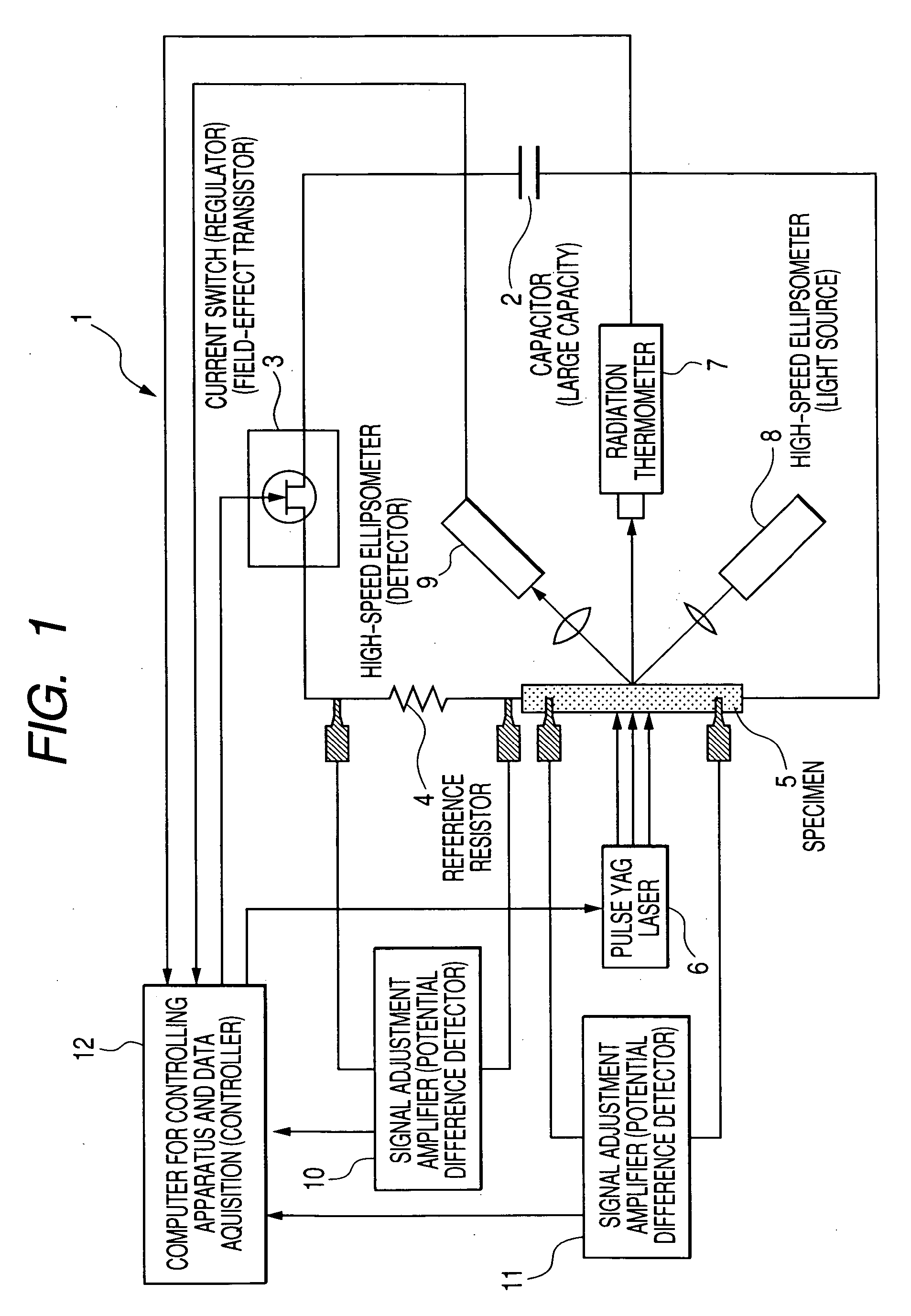
[0084] Measurement was carried out to determine the thermal diffusivity of the following sample with the apparatus shown in FIG. 1.

[0085] Material: Molybdenum (Purity: 99.95%) [0086] Thickness: 0.3 mm [0087] Effective mass: 0.537 g [0088] Effective surface area: 371 mm2

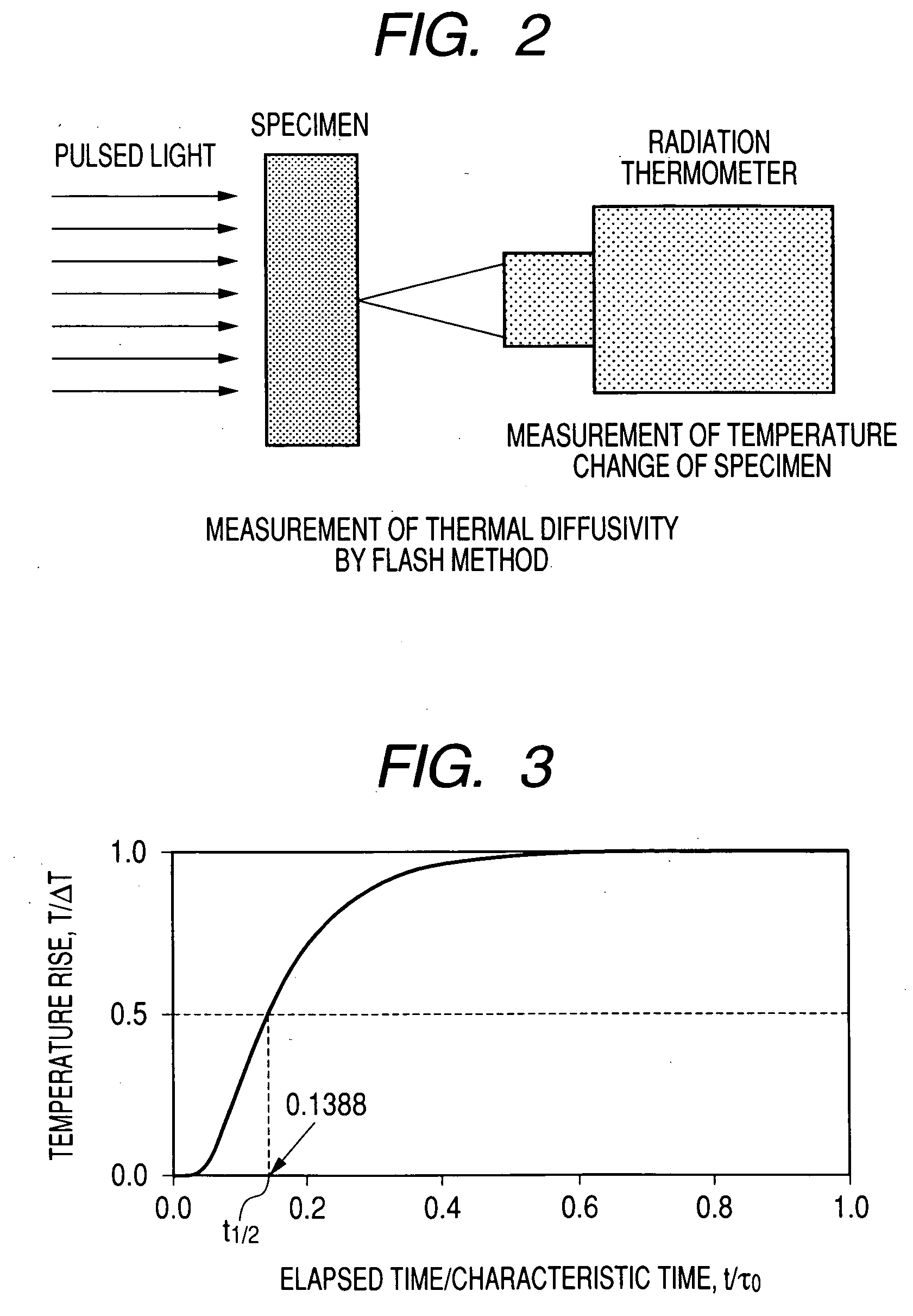
[0089] Results of the measurement are shown in FIGS. 5 and 6. FIG. 6 shows an enlarged view of FIG. 5 at a time of emitting a laser pulse to the specimen. In FIGS. 5 and 6, “Receiving Signal” denotes a signal output from a photo receiver, which is detected in order to determine a time of emitting the laser pulse to the specimen. In FIGS. 5 and 6, a portion in which the signal value is drastically increased shows the time of emitting the laser pulse.

[0090] The ambient temperature in the measurement was 293 K. The constant ...


PUM

PropertyMeasurementUnit
temperaturesaaaaaaaaaa
temperatureaaaaaaaaaa

Abstract

The present invention provides a method for measuring thermophysical properties that includes: rapid resistive self-heating of a specimen by using a heating current; emitting a light to the specimen heated by the rapid resistive self-heating of the specimen; measuring a temperature change of the specimen induced by emitting the light to the specimen; and deriving a thermal diffusivity of the specimen from the temperature change induced by emitting the light to the specimen.

Description

FIELD OF THE INVENTION [0001] The present invention relates to a method and an apparatus for measuring some kinds of thermophysical properties at once, which include the specific heat capacity, the hemispherical total emissivity, the thermal conductivity and the thermal diffusivity, of a material at high temperatures. BACKGROUND OF THE INVENTION [0002] In order to perform a heat transfer analysis for an apparatus that generates heat or for an apparatus used at a high temperature, four thermophysical properties (e.g., specific heat capacity, hemispherical total emissivity, thermal conductivity and thermal diffusivity) of the materials of which the apparatus is made are required. In case that the apparatus is composed of newly developed materials, or those for which reliable data of thermophysical properties are not available, the above described thermophysical properties of the materials need to be experimentally obtained. Since these four thermophysical properties are generally meas...

Claims


Application Information

Patent Timeline
Patent Type & Authority Applications(United States)
IPC IPC(8): G01N25/00G01N25/18
CPCG01N25/18
Inventor WATANABE, HIROMICHIBABA, TETSUYA
Owner NAT INST OF ADVANCED IND SCI & TECH
Why Eureka
Try Eureka