Arrangement for connecting a rod end to a headed pin and method of manufacture

Inactive Publication Date: 2006-02-23
DURA GLOBAL TECH
View PDF26 Cites 18 Cited by
  • Summary
  • Abstract
  • Description
  • Claims
  • Application Information

AI Technical Summary

Benefits of technology

[0008] It is a further object to provide such an arrangement which can be manufactured at low cost.
[0009] It is yet another object to

Problems solved by technology

The vibration isolator is usually constructed of a soft compressible material and excessive lash can result if the isolator material is directly contacted by the pin.
Such connections have been provided by assembling several parts together, and the necessary clearances for assembly also contribute to excessive lash at the connection.
The cost of manufacturing such linkages typica

Method used


Image

  • Arrangement for connecting a rod end to a headed pin and method of manufacture
  • Arrangement for connecting a rod end to a headed pin and method of manufacture
  • Arrangement for connecting a rod end to a headed pin and method of manufacture

Examples


Embodiment Construction

[0024] In the following detailed description, certain specific terminology will be employed for the sake of clarity and a particular embodiment described in accordance with the requirements of 35 USC 112, but it is to be understood that the same is not intended to be limiting and should not be so construed inasmuch as the invention is capable of taking many forms and variations within the scope of the appended claims.

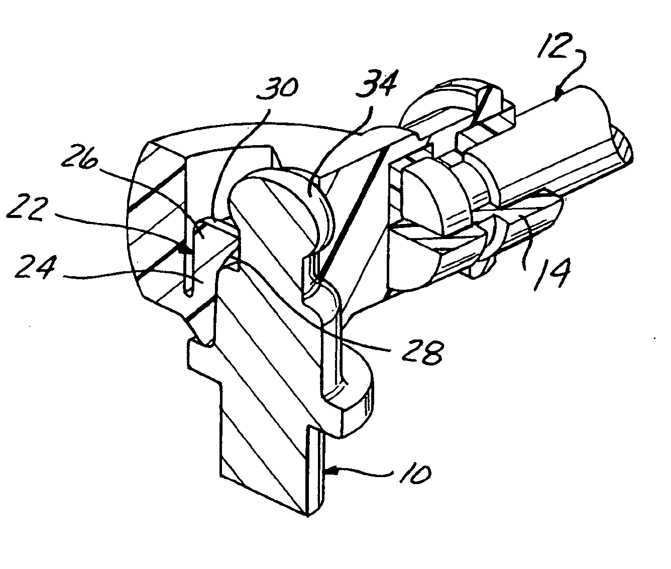
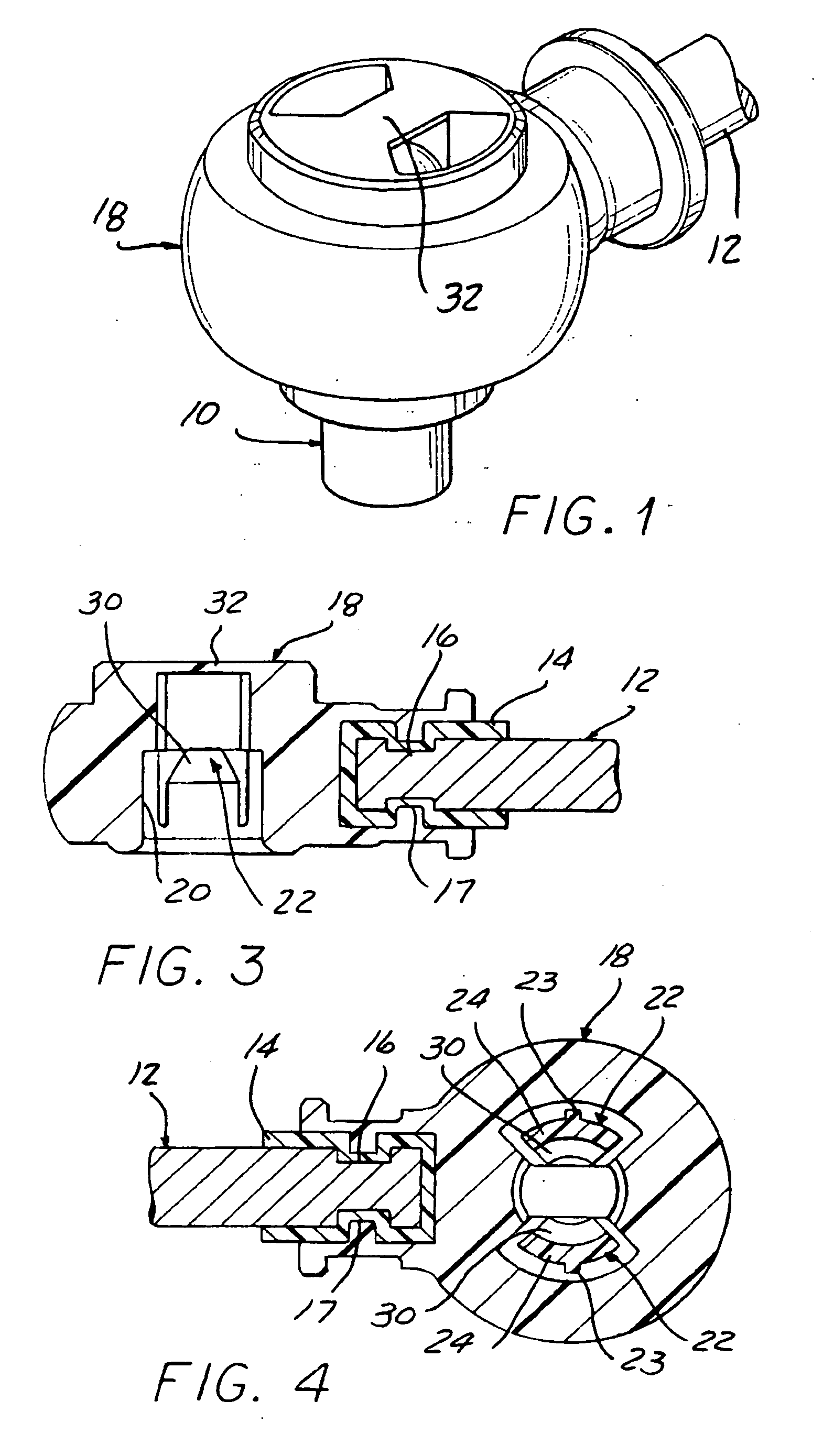
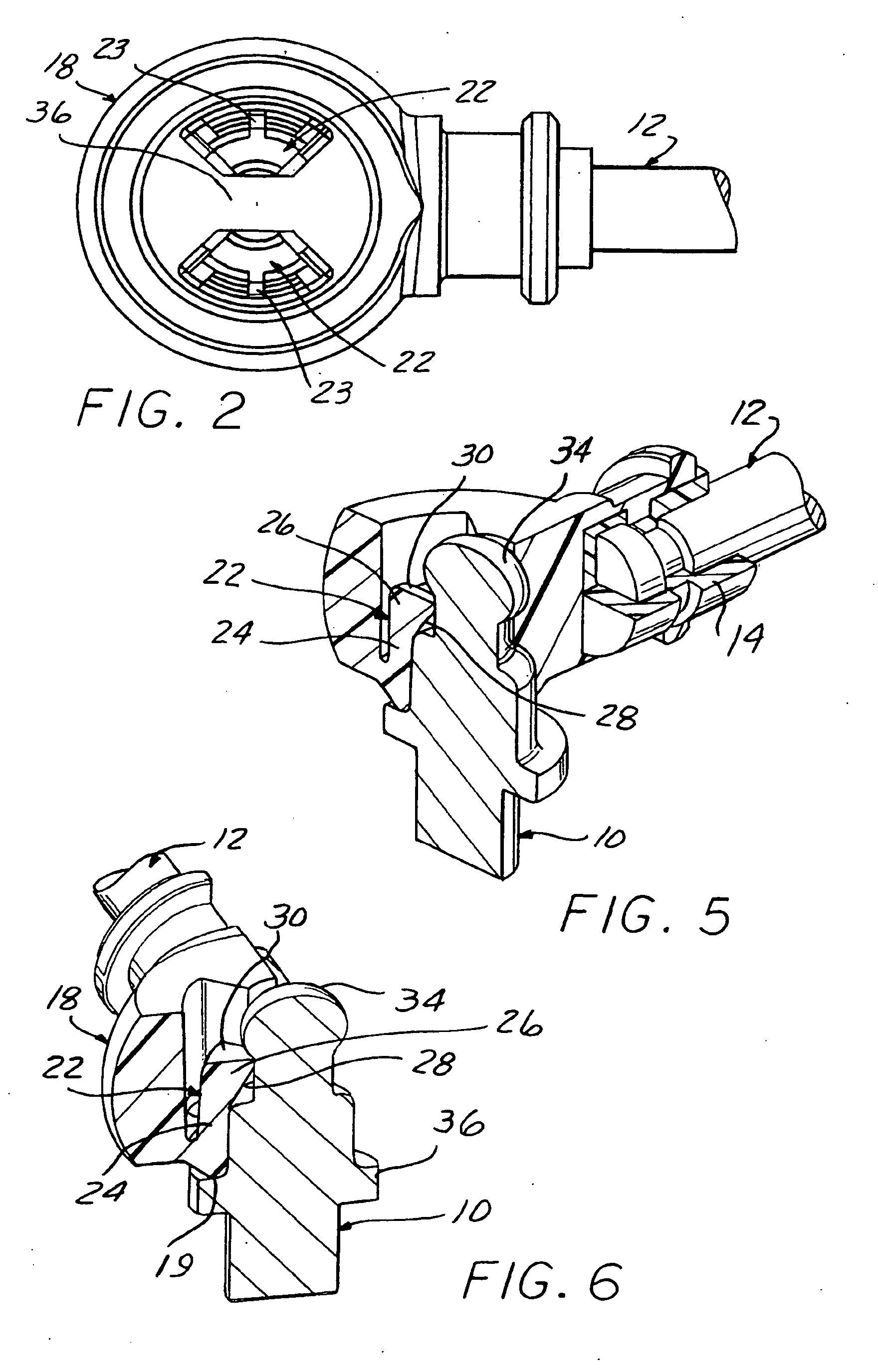
[0025] Referring to the drawings, and particularly FIGS. 1-6, the present invention provides an arrangement for establishing a connection between a headed pin 10 and one end of a steel control rod 12. Such connections are commonly used to couple a transmission control rod to an automotive transmission lever by a pin allowing relative rotation. Other control linkage systems for automotive and other applications widely use such connections which allow a changing angle of the control rod on the pin as it is advanced retracted.

[0026] This connection includes a thin walled...


PUM


Abstract

An arrangement and method of manufacture for providing a connection between one end of a control rod and a headed pin includes a hard plastic housing having a pin receiving cavity defined therein, the housing overmolded over the rod end and a soft elastomeric vibration isolator to hold the same together without assembly clearances or subjecting the vibration isolator to direct pressure from the pin to avoid excessive lash in the connection. Retention prongs are integrally molded and configured to engage the head of the pin when inserted in the cavity to be deflected to allow assembly and thereafter resist extraction, with the insertion forces much lower than the extraction force.

Description

CROSS REFERENCE TO RELATED APPLICATION [0001] This application claims the benefit of U.S. provisional applications Ser. No. 60 / 386,986, filed Jun. 7, 2002 and Ser. No. 60 / 400,082, filed Jul. 31, 2002.BACKGROUND OF THE INVENTION [0002] This invention concerns rod end terminal connections commonly used to connect control rods to pins mounted to automobile transmission levers and the like to enable shifting of the transmission by the driver of the automobile. The pin is retained in a housing by a ball feature head on the pin snap fit to retention features on the housing. It has become standard practice to interpose a vibration isolator between the connected rod and pin to prevent vibrations from being felt by the driver when grasping a shifter or other member. See U.S. Pat. No. 4,581,953 for an example of such a connection. [0003] The vibration isolator is usually constructed of a soft compressible material and excessive lash can result if the isolator material is directly contacted by...

Claims


Application Information

Patent Timeline
IPC IPC(8): F16C11/00F16C11/06
CPCB60G2204/416B60G2206/11F16C1/108F16C1/14F16C11/04F16C2361/65Y10T403/32951Y10T403/32786Y10T403/32631Y10T403/32803Y10T403/69Y10T403/32795Y10T403/5773F16C2226/74
Inventor RUHLANDER, GREGORY P.
Owner DURA GLOBAL TECH
Why Eureka
Try Eureka