Magnetic recording medium and magnetic recording/reproducing apparatus

a recording medium and recording medium technology, applied in the field of magnetic recording medium and magnetic recording/reproducing apparatus, can solve the problems of processing limitations of the magnetic head, come to be known, etc., and achieve the effects of reducing spike-like noise, reducing remanent magnetization at the soft magnetic layer originated from the recording magnetic field, and reducing the noise of spikes

Inactive Publication Date: 2006-02-23
TDK CORPARATION
View PDF5 Cites 30 Cited by
  • Summary
  • Abstract
  • Description
  • Claims
  • Application Information

AI Technical Summary

Benefits of technology

[0014] When however the soft magnetic layer was thus actually formed into a concavo-convex pattern, the recording characteristic changes every time data was recorded or a large spike-like noise that could cause errors during reproducing was generated. In addition, the random noise level increased. This was probably because of change in the direction of the magnetic anisotropy of the soft magnetic layer caused as the soft magnetic layer was processed to have the concavo-convex pattern. More specifically, a soft magnetic layer tends to obtain magnetic anisotropy in the length-wise direction when it is processed to have an elongate shape. Therefore, when the soft magnetic layer is formed into a concavo-convex pattern, the convex part of the soft magnetic layer obtains magnetic anisotropy in the length-wise direction, i.e., in the circumferential direction of the tracks. In other words, it is believed that when the soft magnetic layer is controlled to have magnetic anisotropy in the width direction of the tracks by the anti-ferromagnetic layer provided on its substrate side, the convex portion in the concavo-convex pattern of the soft magnetic layer is provided with magnetic anisotropy in the circumferential direction of the tracks. This causes large magnetization from the recording magnetic field to remain in the soft magnetic layer even after the recording magnetic field is removed. It is believed that this changed the recording characteristic every time data was recorded or a magnetic domain was generated in some magnetization pattern of the recording layer to cause a spike-like noise, and the random noise component increased.
[0016] When, for example, the main component of the recording magnetic field parallel to the surface of the medium in the medium is directed in the circumferential direction that equals the length-wise direction of the tracks, the fixing layer provided on the recording layer side of the soft magnetic layer allows the magnetic anisotropy of the convex portion of the soft magnetic layer to be fixed in the width direction of the tracks perpendicular to the length-wise direction. In this way, the remanent magnetization at the soft magnetic layer originated from the recording magnetic field can be reduced. Alternatively, the high coercive force layer or material is magnetized to constantly apply a magnetic field to the soft magnetic layer in the width direction of the tracks, so that the remanent magnetization at the soft magnetic layer originated from the recording magnetic field can be reduced. Consequently, large remanent magnetization by the recording magnetic field or a magnetic domain in the soft magnetic layer after the removal of the recording magnetic field can be reduced, and the spike-like noise and the like can be reduced.

Problems solved by technology

This may cause noises or the like during reproducing data.
In this case, spike-like noises could be generated during reproducing to cause errors.
Meanwhile, disadvantages such as processing limitations for the magnetic heads, recording to track adjacent to the target track caused by the expansion of the magnetic recording field of the magnetic head and crosstalk during reproducing have come to be known.

Method used


Image

  • Magnetic recording medium and magnetic recording/reproducing apparatus
  • Magnetic recording medium and magnetic recording/reproducing apparatus
  • Magnetic recording medium and magnetic recording/reproducing apparatus

Examples


working example

[0115] Ten magnetic recording media 12 were manufactured according to the first exemplary embodiment. The specific structure of the magnetic recording media 12 will be described below.

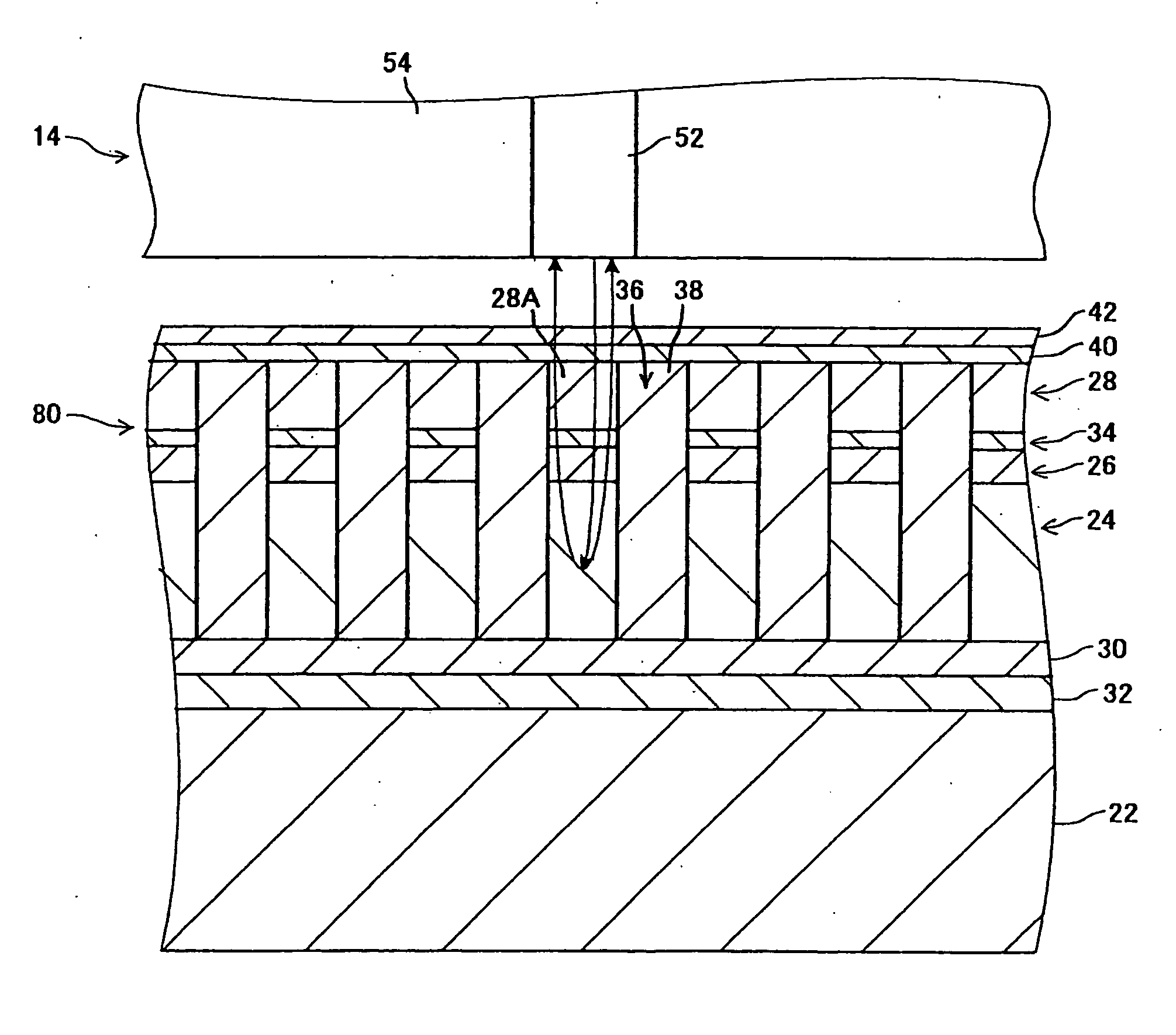
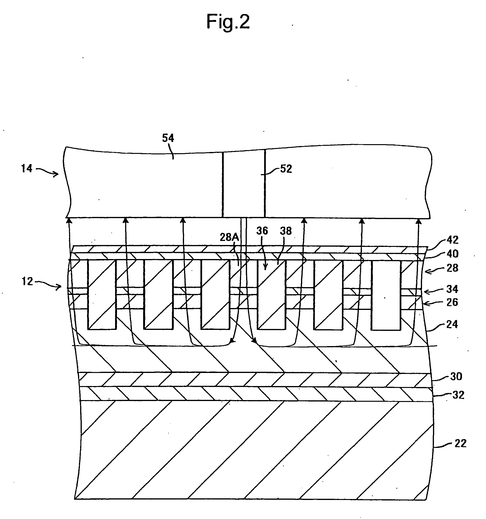
[0116] The substrate 22 had a diameter of about 25.4 mm (1 inch) and was made of glass. The underlayer 32 was about as thick as 10 nm and made of Ta. The second fixing layer 30 was about as thick as 20 nm and made of a PtMn alloy. The soft magnetic layer 24 was about as thick as 100 nm and made of a CoZrNb alloy. The first fixing layer 26 was about as thick as 10 nm and made of a PtMn alloy. The seed layer 34 was about as thick as 10 nm and made of Ru. The recording layer 28 was about as thick as 20 nm and made of SiO2 and CoPt crystal particles in a mixed crystalline phase. The non-magnetic material 38 was SiO2. The protective layer 40 was about as thick as 4 nm and made of DLC. The lubricating layer 42 was about as thick as 1 nm and made of a fluorine containing lubricant.

[0117] The track pitch was...

simulation example 1

[0125] Eight simulation models according to the first exemplary embodiment were produced. Note that these simulation models had concave portions in different depths, and the other structure was the same. The structures of the simulation models are given in Table 1. The depths of the concave portions are shown in Table 2. Note that the main magnetic pole thickness Mt in Table 1 represents the circumferential thickness of the part of the main magnetic pole 52 in the vicinity of the magnetic recording medium 12 as shown in FIG. 4.

TABLE 1Concavo-convexWidth of convex portion100nmpatternWidth of concave portion100nmTrack pitch200nmRecording layerMagnetic perpendicular600kA / manisotropy fieldThickness20nmSaturation magnetization0.5teslaSeed layerThickness10nmFirst fixing layerThickness10nmSoft magneticInitial permeability6.3 × 10−4H / mlayerThickness100nmHeadSaturation magnetization of main2.3teslamagnet poleMagnetomotive force0.12ATMain magnetic pole thickness Mt200nmMain magnetic pole wi...

simulation example 2

[0129] Simulations were run for eight simulation models in the Simulation Example 1, and the result representing the relation was obtained between the thickness ratio of the part of the soft magnetic layer that forms the bottom part of the concave portion relative to the total thickness of the soft magnetic layer and the intensity of the recording magnetic field at the top surface of a recording element as shown in Table 2 and FIG. 16. Note that the intensity of the recording magnetic field refers to the intensity of the recording magnetic field in the center in the track width direction of the top surface of the recording element. The magnitude is represented by its ratio relative to the recording magnetic field at the top surface of the recording layer in a simulation model without a concave portion as 1.

[0130] The relation between the ratio of the part of the soft magnetic layer that forms the bottom part of the concave portion relative to the total thickness of the soft magneti...


PUM

PropertyMeasurementUnit
thicknessaaaaaaaaaa
depthaaaaaaaaaa
thicknessaaaaaaaaaa

Abstract

A perpendicular recording type, magnetic recording medium having a soft magnetic layer and a magnetic recording / reproducing apparatus including such a magnetic recording medium are provided. The magnetic recording medium allows the recording magnetic field to be efficiently applied to a track for recording while restricting the extent of the recording magnetic field. The magnetic recording medium has a soft magnetic layer and a recording layer formed in this order on a substrate. The soft magnetic layer has its part on the opposite side to the substrate formed in a concavo-convex pattern. The recording layer is oriented to have magnetic anisotropy in the direction perpendicular to the surface. A fixing layer for fixing the magnetic anisotropy of the soft magnetic layer in a predetermined direction parallel to the surface is provided between the recording layer and the soft magnetic layer.

Description

BACKGROUND OF THE INVENTION [0001] 1. Field of the Invention [0002] The present invention relates to a perpendicular recording type magnetic recording medium including a soft magnetic layer and a magnetic recording / reproducing apparatus. [0003] 2. Description of the Related Art [0004] The areal densities of conventional magnetic recording media such as a hard disk have been greatly increased as the size of magnetic grains forming the recording layers has been reduced, different materials have been used, and the heads have come to be more precisely processed. Development of perpendicular recording type magnetic recording media for practical use is underway in which a recording layer is oriented to have magnetic anisotropy perpendicular to the surface and a soft magnetic layer is formed under the recording layer, so that the areal density is increased. [0005] In the perpendicular recording type magnetic recording medium, the soft magnetic layer attracts the recording magnetic field fr...

Claims


Application Information

Patent Timeline
Patent Type & Authority Applications(United States)
IPC IPC(8): G11B5/667G11B5/66
CPCG11B5/66G11B5/855G11B5/667G11B5/676
Inventor KAIZU, AKIMASATAGAMI, KATSUMICHISHIMAKAWA, KAZUYA
Owner TDK CORPARATION
Why Eureka
Try Eureka