Fuel cell discharge-gas processing device

a discharge gas and processing device technology, applied in the direction of machines/engines, electrical generators, transportation and packaging, etc., can solve the problems of liquid adhesion to the partition panel, falling, and traveling across the vertically positioned partition panel, so as to simplify the structure of the discharge gas processing device and enhance the drainage performance

Inactive Publication Date: 2006-02-23
HONDA MOTOR CO LTD
View PDF6 Cites 29 Cited by
  • Summary
  • Abstract
  • Description
  • Claims
  • Application Information

AI Technical Summary

Benefits of technology

[0018] The present invention was achieved in view of the above circumstances, and provides a fuel cell discharge-gas processing device that can prevent blow-through of anode off-gas and discharge the anode off-gas with a sufficiently reduced hydrogen concentration, in addition to having a simple construction and excellent mechanical strength and drainage.

Problems solved by technology

This can promote condensation of the steam in the anode off-gas and cause liquid adhering to the partition panel to travel across the vertically positioned partition panel and fall.

Method used


Image

  • Fuel cell discharge-gas processing device
  • Fuel cell discharge-gas processing device
  • Fuel cell discharge-gas processing device

Examples


Embodiment Construction

[0055] Embodiments of the fuel cell discharge-gas processing device of the present invention shall be explained hereinbelow referring to the drawings of FIG. 1 to FIG. 4.

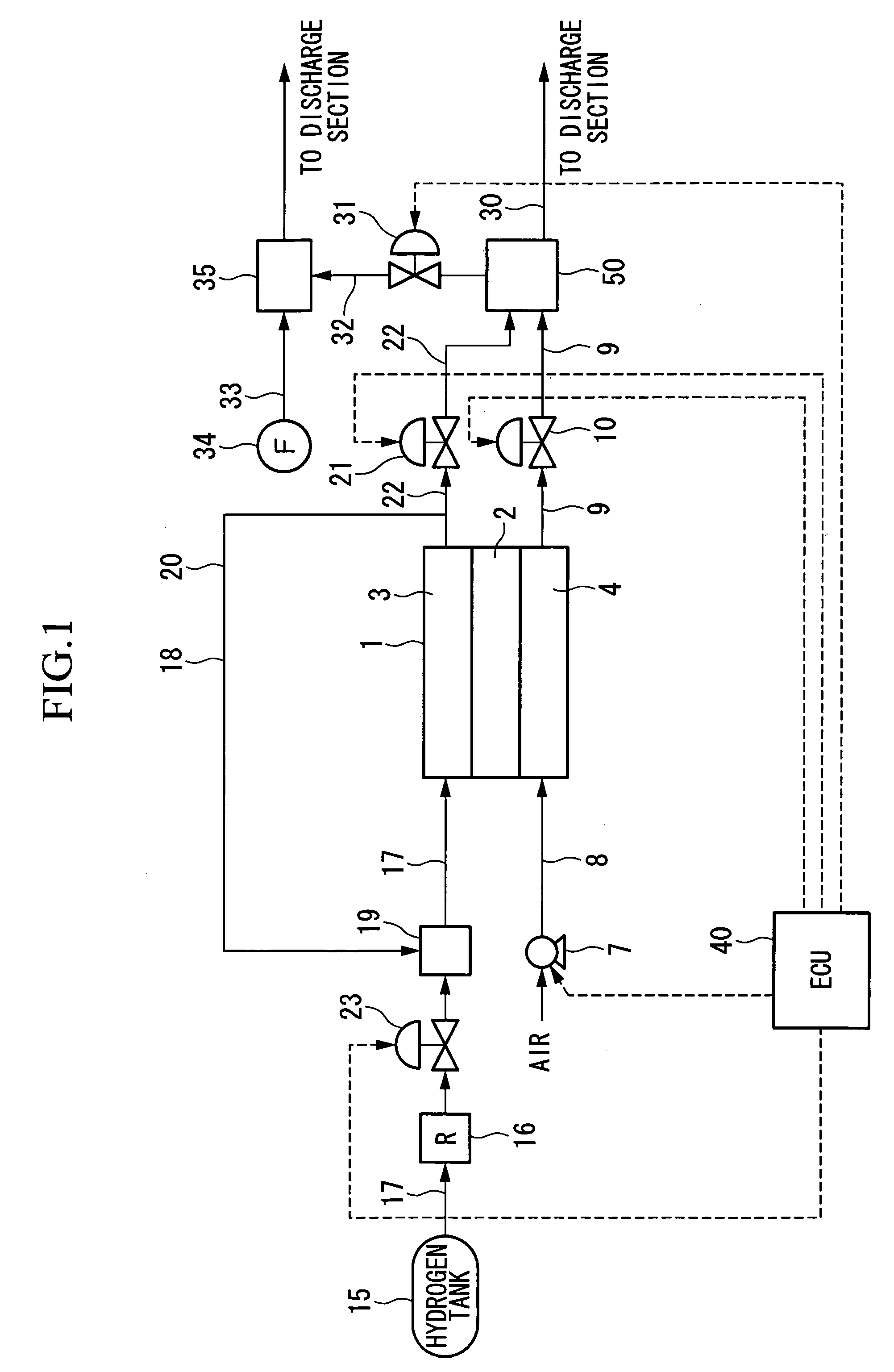
[0056]FIG. 1 is a schematic lineblock diagram of a fuel cell system equipped with the discharge-gas processing device according to this invention, which in this embodiment is mounted in a fuel cell vehicle.

[0057] A fuel cell 1 is of the type that obtains electrical power through chemical reactions of reactant gases. It is constituted by, for example, laminating a plurality of cells formed by sandwiching a solid polymer electrolyte membrane 2 including a solid polymer ion exchange membrane etc. between an anode 3 and a cathode 4 (shown by the single cell in FIG. 1). When hydrogen gas (reactant gas) is supplied to the anode 3 as a fuel gas, and air containing oxygen (reactant gas) is supplied to the cathode 4 as an oxidizing agent gas, hydrogen ions generated by a catalytic reaction in the anode 3 pass the solid pol...


PUM

PropertyMeasurementUnit
perimeteraaaaaaaaaa
electrical poweraaaaaaaaaa
chemical energyaaaaaaaaaa

Abstract

A fuel cell discharge-gas processing device that dilutes anode off-gas discharged from a fuel cell anode by mixing the anode off-gas with a diluent gas so as to produce a diluted gas and then discharges mixture of the anode off-gas and the diluent gas, includes: a dilution container; an anode off-gas introduction path; a diluent gas path through; a diluent gas emission hole; a mixed gas discharge hole; at least one partition panel; and a communication gas path, wherein the anode off-gas emission hole is provided so as to emit anode off-gas toward the partition panel.

Description

BACKGROUND OF THE INVENTION [0001] 1. Field of the Invention [0002] The present invention relates to a discharge-gas processing device that carries out dilution processing of off-gas discharged from a fuel cell. [0003] The present application claims priority on Japanese Patent Application No. 2004-205747, filed Jul. 13, 2004, and Japanese Patent Application No. 2004-205748, filed Jul. 13, 2004, the contents of which are incorporated herein by reference. [0004] 2. Description of Related Art [0005] As a type of fuel cell to be installed in a fuel cell vehicle and the like, a fuel cell is known in which electrical power is generated through chemical reactions of reactant gases. Among such fuel cells, a type of fuel cell is known that provides an anode and a cathode on opposite sides of a solid polymer electrolyte membrane, supplies a fuel gas (e.g., hydrogen gas) to the anode and supplies an oxidizing gas (e.g., air containing oxygen) to the cathode so that chemical energy produced in ...

Claims


Application Information

Patent Timeline
Patent Type & Authority Applications(United States)
IPC IPC(8): H01M8/04B01J19/00
CPCB01F5/0268B01F5/0603H01M8/04156Y02E60/50H01M2008/1095H01M2250/20Y02T90/32H01M8/0662Y02T90/40F01N3/05F01N3/005F01N3/30F01N13/00F01N2240/32F01N2240/22F01N2260/26F01N2570/22F01N2610/06F01N2270/10F01N2470/14F01N2470/16F01N2470/02F01N2490/08F01N2240/20Y02T10/12B01F25/25B01F25/421
Inventor NUMATA, HIDEOYAMAMOTO, AKIONOZAKI, SHUJIROMATSUTANI, MASAHIROFUKUMA, KAZUNORI
Owner HONDA MOTOR CO LTD
Why Eureka
Try Eureka