Nanostructured fuel cell electrode

a fuel cell electrode, nanostructure technology, applied in the direction of cell components, final product manufacturing, sustainable manufacturing/processing, etc., can solve the problem of lower than desired oxygen diffusion through these electrode layers or thin films

Inactive Publication Date: 2006-02-23
BLOOM ENERGY CORP
View PDF11 Cites 76 Cited by
  • Summary
  • Abstract
  • Description
  • Claims
  • Application Information

AI Technical Summary

Benefits of technology

[0006] Another preferred aspect of the present invention provides a method of forming a plurality of metal nanostructures, comprising forming a plurality of m...

Problems solved by technology

However, oxygen diffusion through these ele...

Method used


Image

  • Nanostructured fuel cell electrode
  • Nanostructured fuel cell electrode
  • Nanostructured fuel cell electrode

Examples


Embodiment Construction

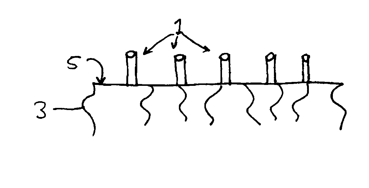
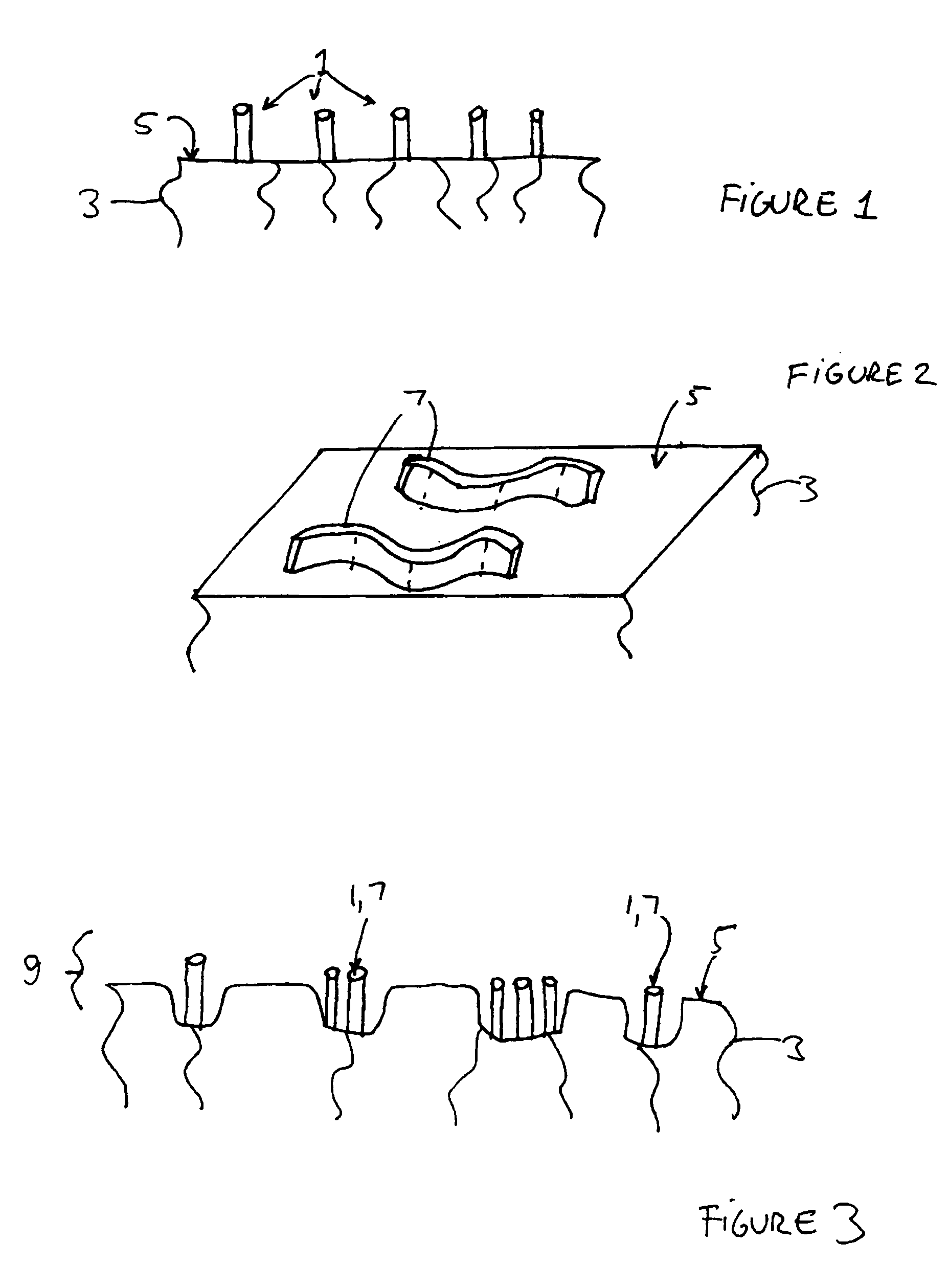
[0012] The present inventor has realized that oxygen diffusion through an electrolyte in a solid oxide fuel cell proceeds between so-called “three phase boundaries.” These three phase boundaries are electrolyte grain boundary regions at the boundary of an electrode (i.e., cathode or anode) and electrolyte. Diffusing oxygen makes up the third “phase.” The present inventor has realized that if one or both electrodes in the fuel cell are formed from nanostructured material, then the surface area between the electrolyte and the electrode contacting the electrolyte surface is increased compared to thin film electrodes. The increased surface area results in more three phase boundary regions, which allows more oxygen to diffuse through the electrolyte. This increases the power density (i.e., watts per cm2) of the fuel cell and decreases the cost per watt of the fuel cell.

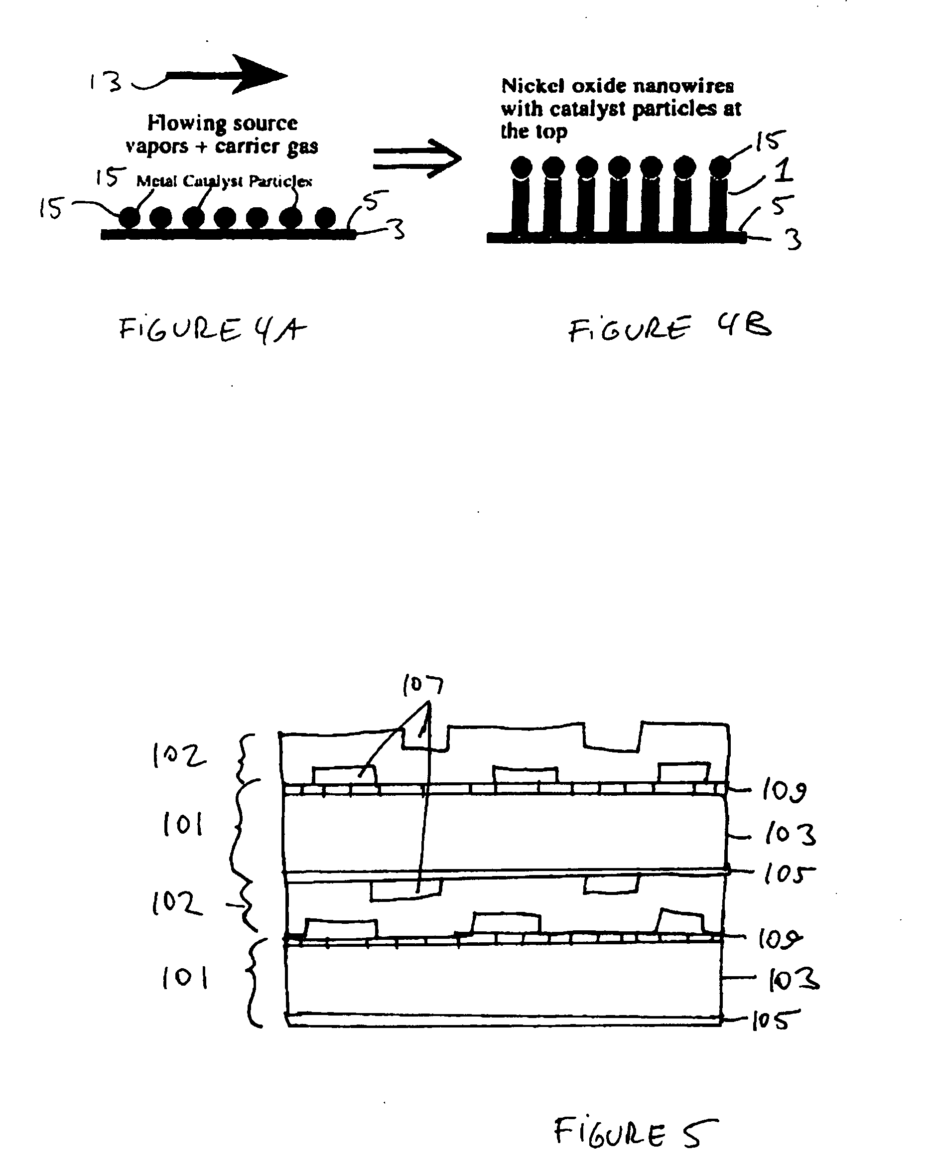
[0013] The term nanostructured material includes quasi-one dimensional nanostructured materials, such as nanowires, nan...


PUM

PropertyMeasurementUnit
Temperatureaaaaaaaaaa
Diameteraaaaaaaaaa
Diameteraaaaaaaaaa

Abstract

A fuel cell includes an electrolyte, a first electrode, and a second electrode. At least the first electrode comprises a nanostructured material.

Description

BACKGROUND OF THE INVENTION [0001] This application claims benefit of priority of U.S. Provisional Application Ser. No. 60 / 602,891, filed Aug. 20, 2004, which is incorporated herein by reference in its entirety.[0002] The present invention is generally directed to fuel cell materials and more specifically to nanowire and other nanostructured electrode materials for solid oxide fuel cells. [0003] Fuel cells are electrochemical devices which can convert energy stored in fuels to electrical energy with high efficiencies. One type of high temperature fuel cell is a solid oxide fuel cell which contains a ceramic (i.e., a solid oxide) electrolyte, such as a yttria stabilized zirconia (YSZ) electrolyte. An anode electrode is formed on one side of the electrolyte and a cathode electrode is formed on the opposite side of the electrolyte. In a non-reversible fuel cell, the anode electrode is exposed to the fuel flow, such as hydrogen or hydrocarbon fuel flow, while the cathode electrode is ex...

Claims


Application Information

Patent Timeline
IPC IPC(8): H01M4/86H01M8/12C01B13/14C30B23/00C23C16/00
CPCB82Y30/00Y02E60/525C01G1/02C01G25/02C01G53/04C01P2004/13C01P2004/16C01P2004/17C01P2006/40C30B23/007C30B25/005C30B29/62H01M4/8626H01M4/881H01M4/8867H01M4/8882H01M4/9025H01M4/9041H01M4/905H01M8/1213H01M8/124H01M2008/1293Y02E60/521C01B13/20Y02E60/50Y02P70/50
Inventor SRIDHAR, K. R.
Owner BLOOM ENERGY CORP
Why Eureka
Try Eureka