Method of fabricating a flat panel direct methanol fuel cell

a fuel cell and flat panel technology, applied in the field of fuel cells, can solve the problems of unwieldy and thick platelet assembly of b>12/b>, and achieve the effect of saving costs

Inactive Publication Date: 2006-02-23
NAN YA PRINTED CIRCUIT BOARD CORPORATION +1
View PDF1 Cites 39 Cited by
  • Summary
  • Abstract
  • Description
  • Claims
  • Application Information

AI Technical Summary

Benefits of technology

[0012] It is another object of the present invention to provide a method for fabricating a thin and highly integrated DMFC, thereby allowing mass product

Problems solved by technology

First, the bipolar platelet assembly 12

Method used


Image

  • Method of fabricating a flat panel direct methanol fuel cell
  • Method of fabricating a flat panel direct methanol fuel cell
  • Method of fabricating a flat panel direct methanol fuel cell

Examples


Embodiment Construction

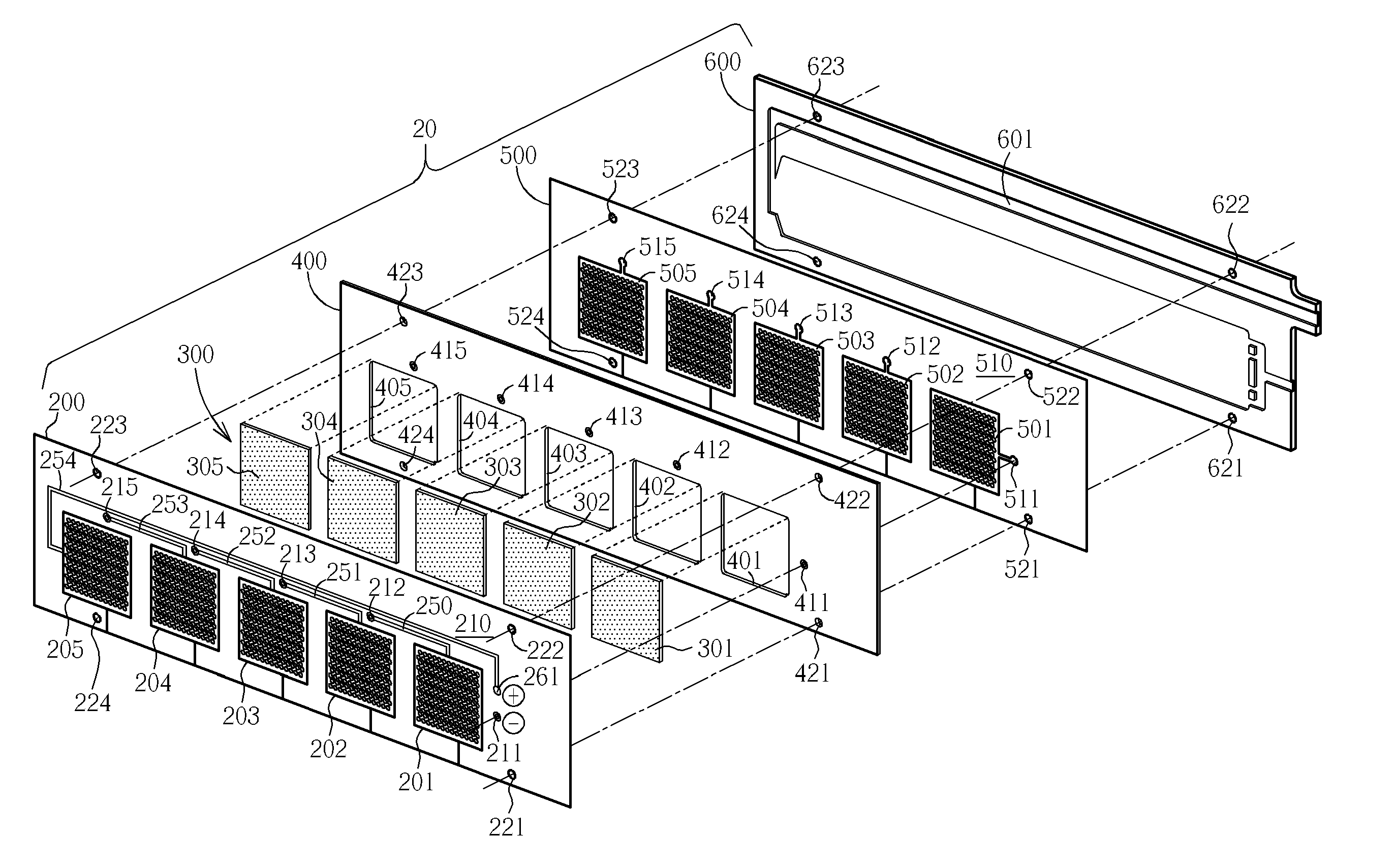
[0033] Please refer to FIG. 3. FIG. 3 is an exploded perspective diagram illustrating a flat panel DMFC 20 with five serially connected basic cell units in accordance with one preferred embodiment of the present invention. It is to be understood that the flat panel DMFC 20 with five serially connected basic cell units is merely an exemplary embodiment. Depending on the requirements of the applied apparatuses, other numbers of basic cell units such as ten or twenty may be used. As shown in FIG. 3, the present invention flat panel DMFC 20 generally comprises an integrated thin cathode electrode plate 200, membrane electrode assembly (MEA) unit 300, intermediate bonding layer 400, integrated thin anode electrode plate 500, and a fuel container 600.

[0034] The integrated thin cathode electrode plate 200 comprises a substrate 210, cathode electrode areas 201, 202, 203, 204, and 205, and conductive through holes 211, 212, 213, 214, and 215. Preferably, on the surface area of the substrate...


PUM


Abstract

A flat panel direct methanol fuel cell (DMFC) includes an integrated cathode electrode plate, a set of membrane electrode assemblies, an intermediate bonding layer, an integrated anode electrode plate, and a fuel container base. The integrated cathode/anode electrode plates are conducive to mass production, and are manufactured by using PCB compatible processes.

Description

BACKGROUND OF INVENTION [0001] 1. Field of the Invention [0002] The present invention relates generally to the field of fuel cells. More particularly, the present invention relates to a flat panel direct methanol fuel cell (DMFC) and method of making the same. [0003] 2. Description of the Prior Art [0004] A fuel cell is an electrochemical cell in which a free energy change resulting from a fuel oxidation reaction is converted into electrical energy. Fuel cells utilizing methanol as fuel are typically called direct methanol fuel cells (DMFCs), which generate electricity by combining aqueous methanol with air. DMFC technology has become widely accepted as a viable fuel cell technology that offers itself to many application fields such as electronic apparatuses, vehicles, military equipment, the aerospace industry, and so on. [0005] DMFCs, like ordinary batteries, provide DC electricity from two electrochemical reactions. These reactions occur at electrodes (or poles) to which reactant...

Claims


Application Information

Patent Timeline
IPC IPC(8): H01M4/86H01M8/10H01M2/08H01M8/24H01M4/96H01M4/88H01M8/00H01M8/02
CPCH01M4/8657H01M8/0273H01M8/1011Y02E60/50H01M8/246Y02E60/523H01M8/1097Y02P70/50H01M8/2404H01M8/2418
Inventor LIU, YUNG-YISHANG, JAMESHO, SHING-FUNCHANG, TSANG-MINGDENG, FENG-YISHU, HSI-MING
Owner NAN YA PRINTED CIRCUIT BOARD CORPORATION
Why Eureka
Try Eureka