Electric propulsion unit

a technology of electric propulsion unit and electric motor, which is applied in the direction of marine propulsion, cell components, vessel construction, etc., can solve the problems of inability to mount electric motors with higher output, generally not having such a sufficient capacity to extend the cruising range, etc., and achieve the effect of preventing downsizing

Active Publication Date: 2006-02-23
YAMAHA MARINE KK
View PDF4 Cites 18 Cited by
  • Summary
  • Abstract
  • Description
  • Claims
  • Application Information

AI Technical Summary

Benefits of technology

[0007] An aspect of at least one of the embodiments disclosed herein includes the realization that in the boats having an outboard motor with an internal combustion engine as a propuls

Problems solved by technology

However, batteries generally do not have such a sufficient capacity as to exte

Method used


Image

  • Electric propulsion unit
  • Electric propulsion unit
  • Electric propulsion unit

Examples


Embodiment Construction

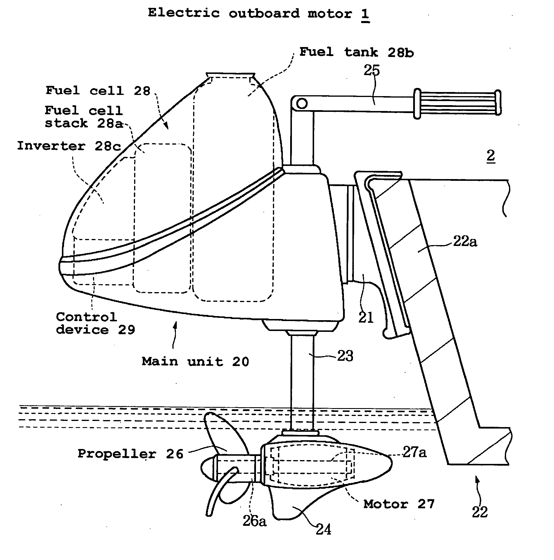
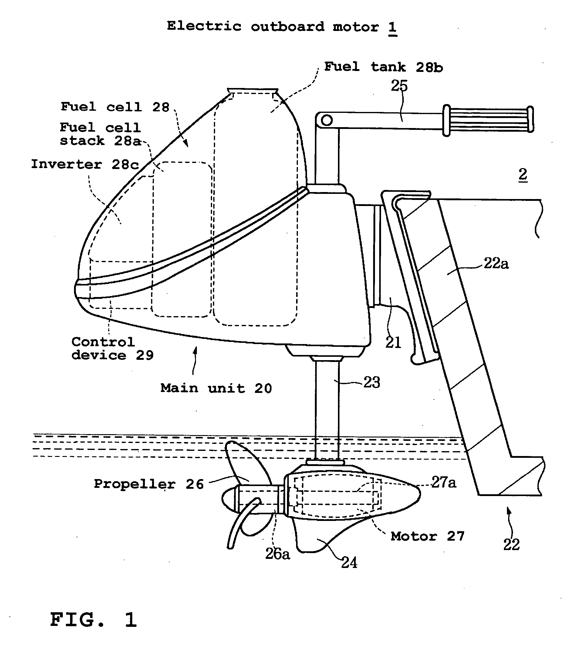
[0027]FIG. 1 shows a configuration of an outboard motor 1 having a fuel cell powered electric motor. This fuel cell powered electric motor arrangement is illustrated as being used with the outboard motor 1 because it has particular utility in this context. However, the present fuel cell powered electric motor arrangements can be used in other contexts, such as, for example, but without limitation, electric inboard motors, electric inboard-outboard motors and the like.

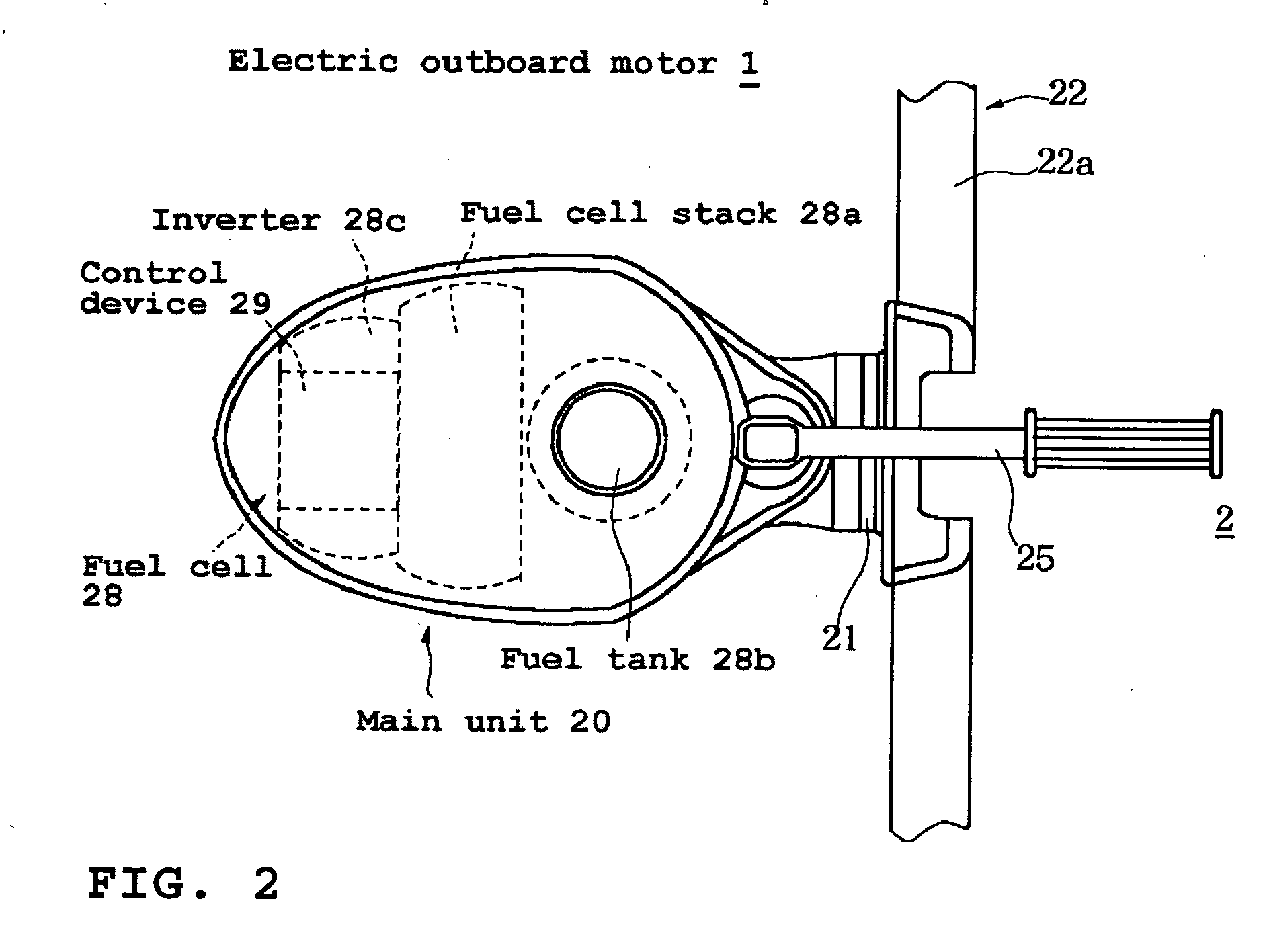
[0028]FIGS. 1 and 2 show a first embodiment. FIGS. 1 and 2 show a boat on which the electric outboard motor 1 is mounted. The electric outboard motor 1 of this embodiment has a main unit 20 provided on a mounting bracket 21. The mounting bracket 21 is fixed to a transom 22a of a hull 22.

[0029] The main unit 20 can include a support tube 23. A lower case 24 can be provided at a lower side of the support tube 23. An operating handle 25 can be provided at an upper side thereof.

[0030] By manipulating the operating handle...


PUM


Abstract

An electric propulsion unit can include a propeller for producing thrust, a motor for driving the propeller, and a fuel cell for supplying electric power to drive the motor. The fuel cell can include a fuel cell stack for generating power and a fuel tank for feeding fuel to the fuel cell stack.

Description

PRIORITY INFORMATION [0001] This application claims priority to Japanese patent application Serial No. 2004-242629, filed on Aug. 23, 2004, the entire contents of which is hereby expressly incorporated by reference. BACKGROUND OF THE INVENTIONS [0002] 1. Field of the Inventions [0003] The present inventions relate to propulsion units for watercraft, and more particularly, electric propulsion units mountdable on boats. [0004] 2. Description of the Related Art [0005] Some boats utilize an outboard motor as a propulsion device. Most outboard motors include an internal combustion engine driving a propeller for generating thrust. In these arrangements, a fuel tank for the internal combustion engine is disposed in the watercraft and is connected to the internal combustion engine with a flexible fuel line. [0006] Other types of outboard motors utilize an electric motor for driving the propeller. Most of these types of outboard motors are configured for low power output and thus are typical...

Claims


Application Information

Patent Timeline
IPC IPC(8): B63H21/21H01M8/00
CPCY02T90/38B63H20/00B63H2021/003Y02E60/50H01M2250/20Y02T90/32H01M8/04201Y02T90/40B63H20/007
Inventor KOBAYASHI, NOBORUKAWAI, TAKAOMATSUSHITA, YUKIO
Owner YAMAHA MARINE KK
Why Eureka
Try Eureka