Mixer capable of detecting or controlling common mode voltage thereof

a technology of mixers and common modes, applied in the direction of electric/magnetic computing, instruments, computations using denominational number representations, etc., can solve the problems of affecting the voltage gain of mixers. , to achieve the effect of reducing the influence of the voltage gain of mixers

Active Publication Date: 2006-02-23
REALTEK SEMICON CORP
View PDF13 Cites 9 Cited by
  • Summary
  • Abstract
  • Description
  • Claims
  • Application Information

AI Technical Summary

Benefits of technology

[0006] It is an objective of the claimed invention to provide a mixer that reduces the influence to the voltage gain of mixers caused by the manufacturing process and temperature variations.

Problems solved by technology

The utilization of operational amplifiers in mixers of the prior art results in more noises.
Unfortunately, the influence to the voltage gain of the mixers by the manufacturing processes and temperature variations remains.
Unfortunately, the same problem of the influence to the voltage gain of the mixer caused by the manufacturing processes and temperature variations still exists.

Method used


Image

  • Mixer capable of detecting or controlling common mode voltage thereof
  • Mixer capable of detecting or controlling common mode voltage thereof
  • Mixer capable of detecting or controlling common mode voltage thereof

Examples


first embodiment

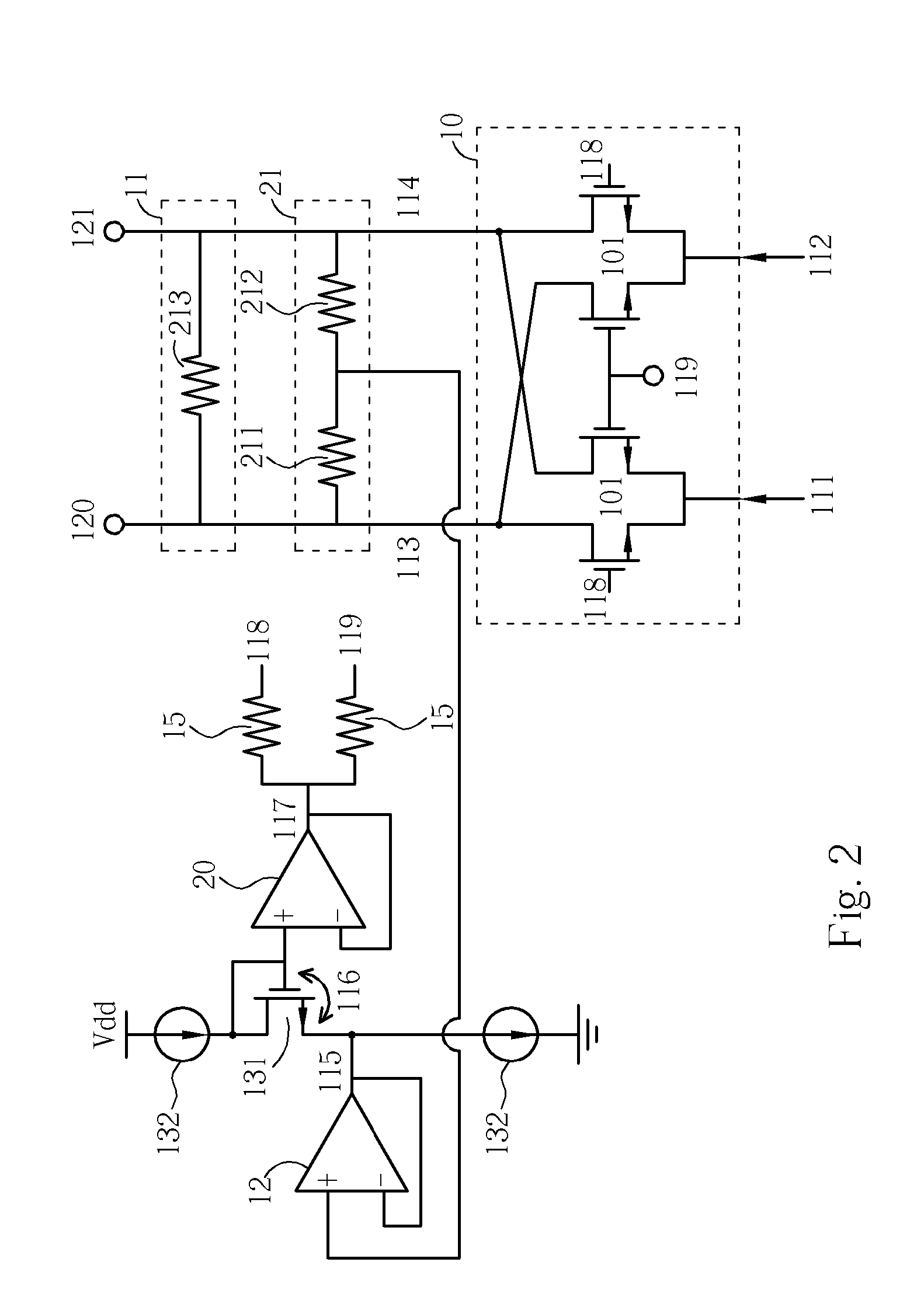
[0018] Please refer to FIG. 2. FIG. 2 is a diagram of a mixer according to the present invention. According to this embodiment, the common mode voltage generator 100d derives the common mode voltage of the I / O terminals 113 and 114 by utilizing two resistors 211 and 212 with the same resistance value, and outputs the common mode voltage 115 by utilizing a DC voltage buffer 12. According to this embodiment, the compensation module 100c shown in FIG. 1 is implemented by coupling the reference transistor 131 to the DC voltage buffer 12, superposing the common mode voltage 115 and the gate-to-source voltage 116 of the reference transistor 131, utilizing another DC voltage buffer 20 to generate the synthesized voltage 117 of this embodiment, and outputting the synthesized voltage 117 to the input terminals 118 and 119 utilizing the two resistors 15 shown in FIG. 2. The I / V converter 111 of this embodiment is a resistor 213, which is well known in the art.

second embodiment

[0019] Please refer to FIG. 3. FIG. 3 is a diagram of a mixer according to the present invention. According to this embodiment, the RF signals are inputted to the switching transistor circuit 10 through two AC coupling capacitors 30 and 31 respectively coupled to the input terminals 111 and 112. The I / V converter 11 of this embodiment includes two transconductor transistors 309 and 310, two loading resistors 305 and 306, and two feedback resistors 307 and 308. With the symmetry of the components 305-310 shown in FIG. 3, a total current flowing through a drain and a source of a transistor 300 is double of an average current flowing through a drain and a source of the transconductor transistor 309, and is also double of an average current flowing through a drain and a source of the transconductor transistor 310. One of the two relationships mentioned above is taken as an example for explanation. The common mode voltage generator 100d of this embodiment includes a common mode voltage f...

third embodiment

[0020] Please refer to FIG. 4. FIG. 4 is a diagram of a mixer according to the present invention. The I / V converter 11 of this embodiment includes two loading resistors, 401 and 402, and an operational amplifier 403, which is a differential operational amplifier. The operational amplifier 403 includes a common mode voltage input terminal CM for controlling the common mode voltage of the output signals of the I / V converter 11. In this embodiment, the common mode voltage can be controlled by an external signal, such as the reference voltage 40 inputted into the common mode voltage input terminal CM. Other similar descriptions are omitted here.


PUM


Abstract

A mixer capable of detecting or controlling a common mode voltage thereof, includes at least: a mixing module for mixing a first set of differential signals and a second set of differential signals to generate at least one mixed signal; and a compensation module for compensating at least one operation point of the mixing module.

Description

BACKGROUND OF THE INVENTION [0001] 1. Field of the Invention [0002] The present invention relates to an up-converter or a down-converter in a communication system, and more particularly, to a mixer capable of detecting or controlling a common mode voltage thereof. [0003] 2. Description of the Prior Art [0004] An up-converter or a down-converter in a communication system generally includes a mixer, and a passive mixer is typically utilized. A switching transistor of a passive mixer operates in a non-saturation region. The passive mixer is utilized in a direct down conversion receiver because it is cost-effective. [0005] The utilization of operational amplifiers in mixers of the prior art results in more noises. Some complementary mixers may balance input signals, however, voltage gains of mixers are influenced by manufacture processes and temperature variations. One method to solve this problem is increasing the linearity of a mixer by increasing a linear region of transconductance o...

Claims


Application Information

Patent Timeline
Patent Type & Authority Applications(United States)
IPC IPC(8): H04B1/18H04B1/26H03D7/14
CPCH03D7/1441H03D7/1458H03D7/1466H03D2200/0088H03D2200/0033H03D2200/0043H03D2200/0025
Inventor LIN, YING-HSI
Owner REALTEK SEMICON CORP
Why Eureka
Try Eureka