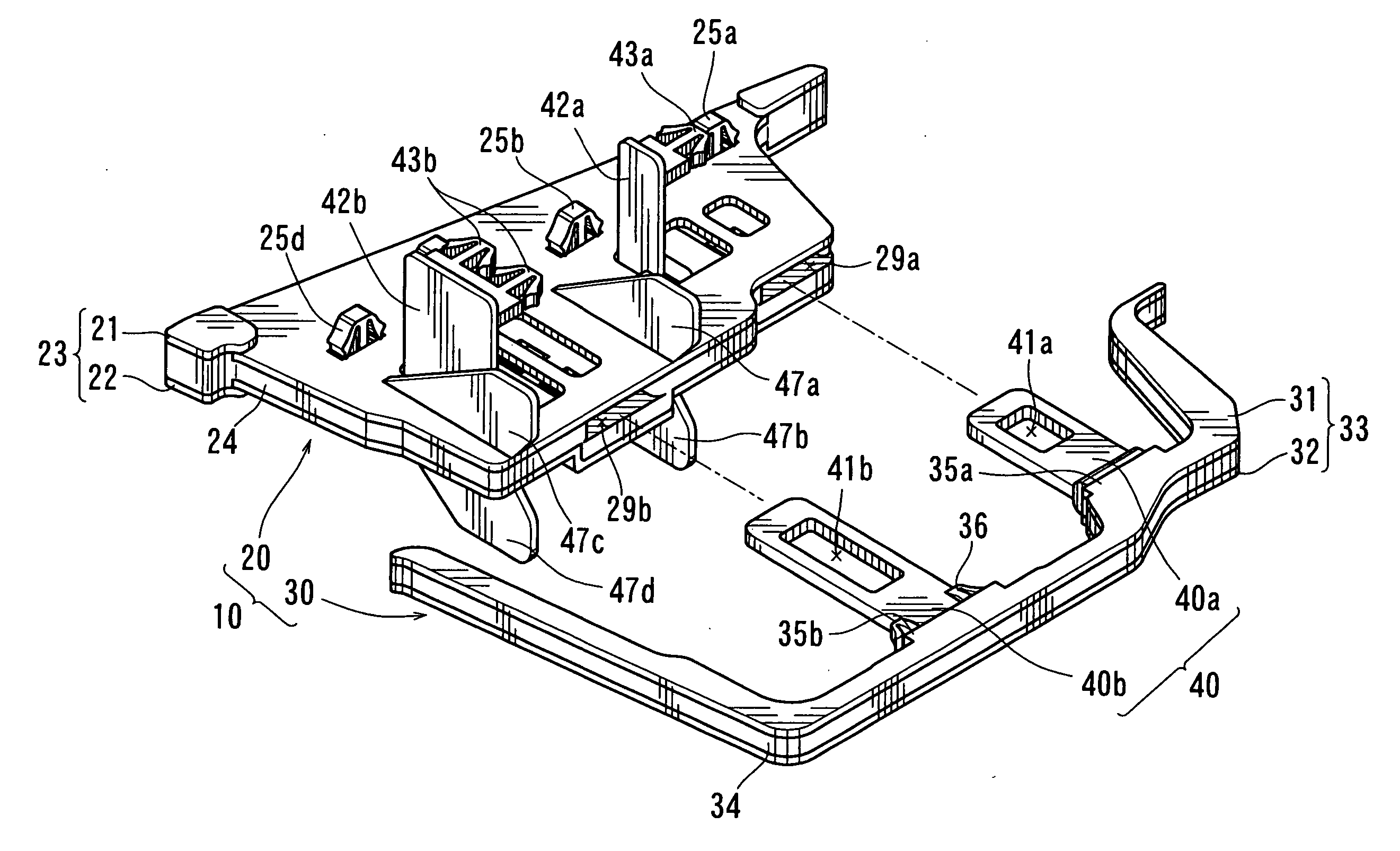
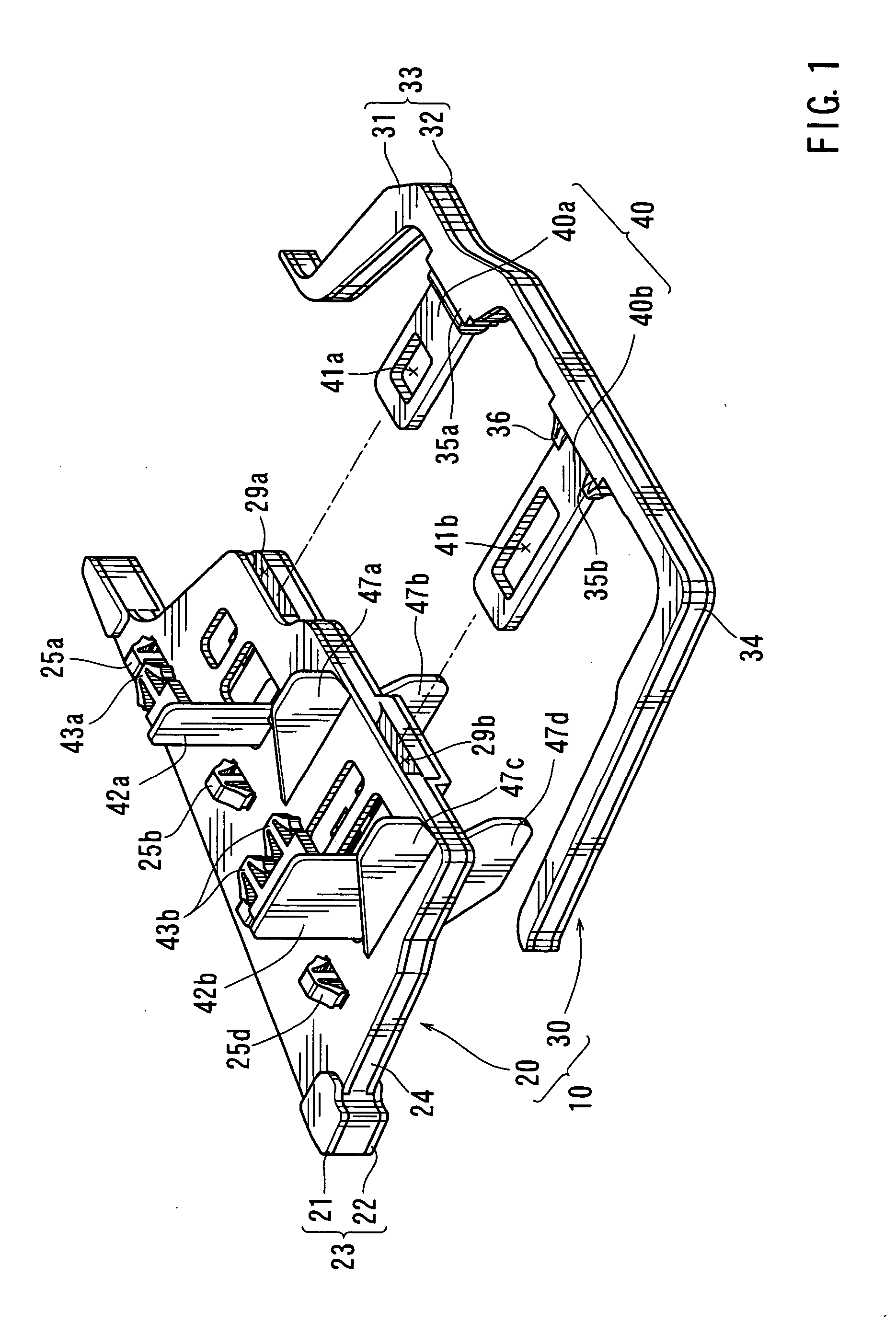
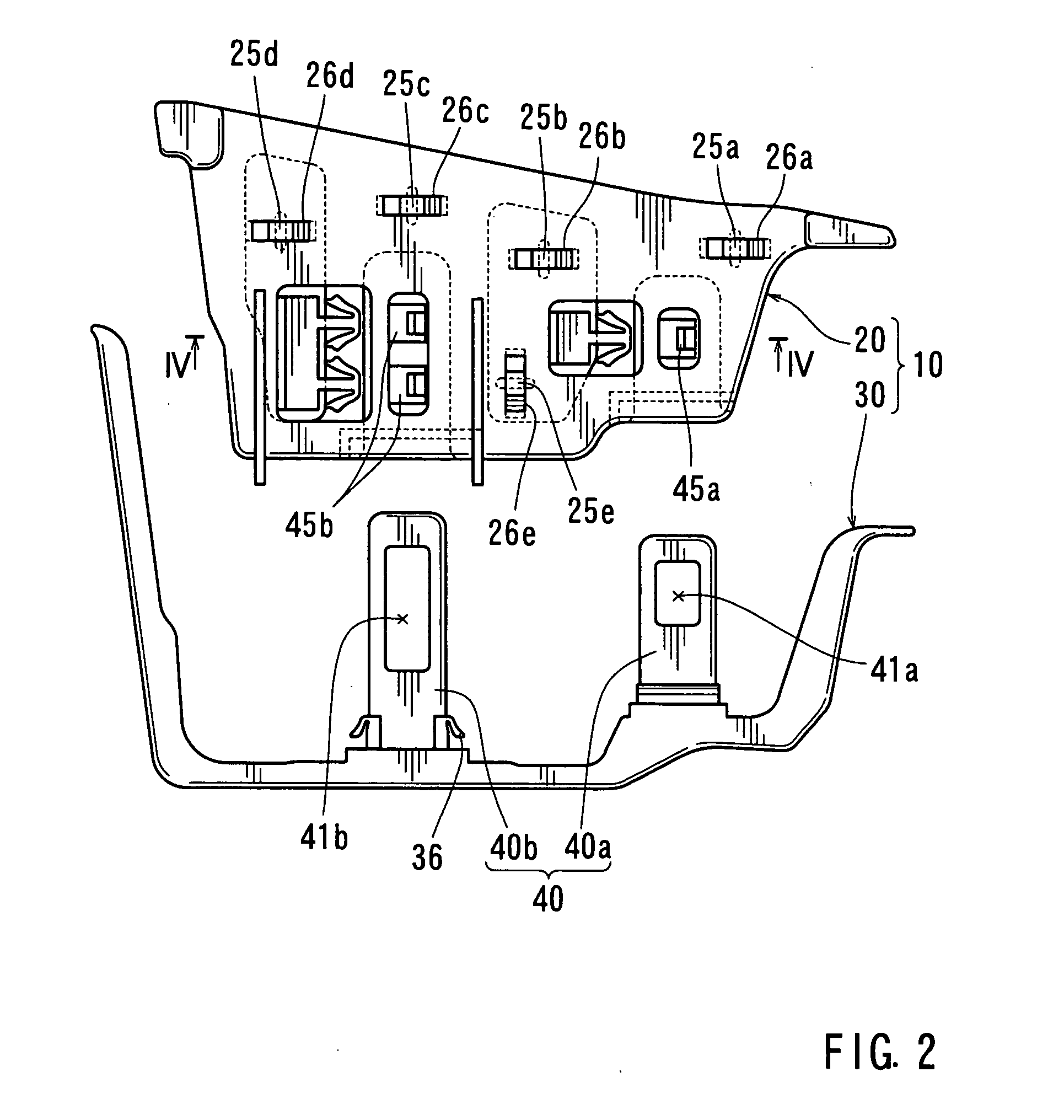
Devices for blocking spaces defined within hollow structures
a technology of hollow structure and space, which is applied in the direction of surgery, vehicle components, transportation and packaging, etc., can solve the problems of insufficient mounting strength of the blocking member to the wall of the hollow structure, and inability to reliably block the space with the expanded foam member. , to achieve the effect of preventing the first and second holder plates from being accidentally removed from each other, reducing the manufacturing cost of the blocking device, and easy
- Summary
- Abstract
- Description
- Claims
- Application Information
AI Technical Summary
Benefits of technology
Problems solved by technology
Method used
Image
Examples
modification 1
(Modification 1)
[0048] According to Modification 1 shown in FIGS. 8(a) and 8(b), a clip or a resilient engaging member 61 is integrally formed with an end portion of a connecting member 60. As shown in FIG. 8(a), the engaging member 61 is formed by cutting out a substantially U-shaped slot in the end portion of the connecting member 61 and bending a portion surrounded by the U-shaped slot upward, as viewed in FIG. 8(b). An insertion hole 63, formed in an expandable member 64 of the blocking member 20, has a stepped portion 62 formed on the upper wall as viewed in FIG. 8(b) of the insertion hole 63. This allows the engaging member 61 to engage with the stepped portion 62 when the connecting member 60 has been inserted into the insertion hole 63. With this arrangement, the fixing member 30 can be very easily connected to the blocking member 20 by the connecting member 60. In addition, it is possible to easily prevent the connecting member 61 from being inadvertently removed from the i...
modification 2
(Modification 2)
[0049] According to Modification 2 shown in FIGS. 9(a) and 9(b), a pair of resilient engaging members 71 that may form a clip together are formed integrally with an end portion of a connecting member 70. As shown in FIG. 9(a), the engaging members 71 extend from the terminal end of the connecting member 70 in a turn-back manner. An insertion hole 73 formed in an expandable member 74 of the blocking member 20 has stepped portions 72 formed on the upper and lower walls, as viewed in FIG. 9(b), of the insertion hole 73. This allows the engaging members 71 to engage with the stepped portions 72 when the connecting member 70 has been inserted into the insertion hole 73. Also with this arrangement, the fixing member 30 can be very easily connected to the blocking member 20 by the connecting member 70. In addition, it is possible to easily prevent the connecting member 71 from being inadvertently removed from the insertion hole 73.
modification 3
(Modification 3)
[0050] According to Modification 3 shown in FIGS. 10(a) and 10(b), an end portion of a connecting member 80 is configured as a clip or an engaging member 85 having a rounded front end. Stepped portions 81 are formed on the rear side of the engaging member 85. Correspondingly, resilient engaging members 82 are integrally formed with the upper and lower walls, as viewed in FIGS. 10(a) and 10(b), of an insertion hole 83 that is formed in an expandable member 84 of the blocking member 20. Therefore, the engaging members 82 may engage with the stepped portions 81 of the engaging member 85 when the connecting member 80 has been inserted into the insertion hole 83 as shown in FIG. 10(b). Also with this arrangement, the fixing member 30 can be very easily connected to the blocking member 20 by the connecting member 80. In addition, it is possible to easily prevent the connecting member 81 from being inadvertently removed from the insertion hole 83.
(Other Possible Modificat...
PUM
 Abstract
Description
Claims
Application Information
 - R&D
- Intellectual Property
- Life Sciences
- Materials
- Tech Scout
- Unparalleled Data Quality
- Higher Quality Content
- 60% Fewer Hallucinations
Browse by: Latest US Patents, China's latest patents, Technical Efficacy Thesaurus, Application Domain, Technology Topic, Popular Technical Reports.
© 2025 PatSnap. All rights reserved.Legal|Privacy policy|Modern Slavery Act Transparency Statement|Sitemap|About US| Contact US: help@patsnap.com


