Vessel isolation device

a technology of a venous isolation device and a vascular abnormality, which is applied in the field of vascular abnormalities treatment devices, can solve the problems of limiting the amount of oxygenated, affecting the treatment effect, and almost certain deaths, and achieves the effect of less handling

Active Publication Date: 2006-02-23
MEDTRONIC VASCULAR INC
View PDF17 Cites 34 Cited by
  • Summary
  • Abstract
  • Description
  • Claims
  • Application Information

AI Technical Summary

Benefits of technology

[0014] A further advantage of the present invention arises from the use of an expansion mechanism other than inflation of a balloon with a fluid. The present invention does not require an inflation lumen so the central lumen may allow more blood to flow through the device. Furthermore, blood is not forced through small orifices of a rigid tube, as in other devices.
[0015] In addition, the present invention may employ a self-expanding body. The self-expanding body would require less handling than a device biased to a collapsed configuration in order to maintain proper deployment. Since the device would maintain itself in the expanded state, it would only require manipulation during the initial deployment and at the time of retraction.

Problems solved by technology

If left untreated, aneurysms may rupture leading to almost certain fatality.
A major disadvantage of conventional treatments for aneurysms has been that the blood flow through the affected vessel had to be blocked in order to perform the treatments efficiently.
Such a narrowing of a vessel limits the amount of oxygenated blood reaching downstream organs and may trigger other medical conditions such as heart attacks.
Unfortunately, the treatments for stenoses often suffer from problems similar to those associated with the treatment of aneurysms.
Those isolation devices presented many disadvantages.
First, the reliance on balloons as the sealing mechanism required that additional hardware be connected to the catheter outside of the patient's body, which makes it more cumbersome to make and use a small catheter.
Second, catheters relying on balloons requires additional care to assure fluid tight seals are created during manufacture.
In addition, balloon catheters pose a risk of fluid leakage from the balloon during use resulting in the loss of the seal between the balloon and the vessel wall.

Method used


Image

  • Vessel isolation device
  • Vessel isolation device
  • Vessel isolation device

Examples


Embodiment Construction

[0029] The present invention is now described with reference to the figures where like reference numbers indicate identical or functionally similar elements. Also in the figures, the left most digit of each reference number corresponds to the figure in which the reference number is first used. While specific configurations and arrangements are discussed, it should be understood that this is done for illustrative purposes only. A person skilled in the relevant art will recognize that other configurations and arrangements can be used without departing from the spirit and scope of the invention.

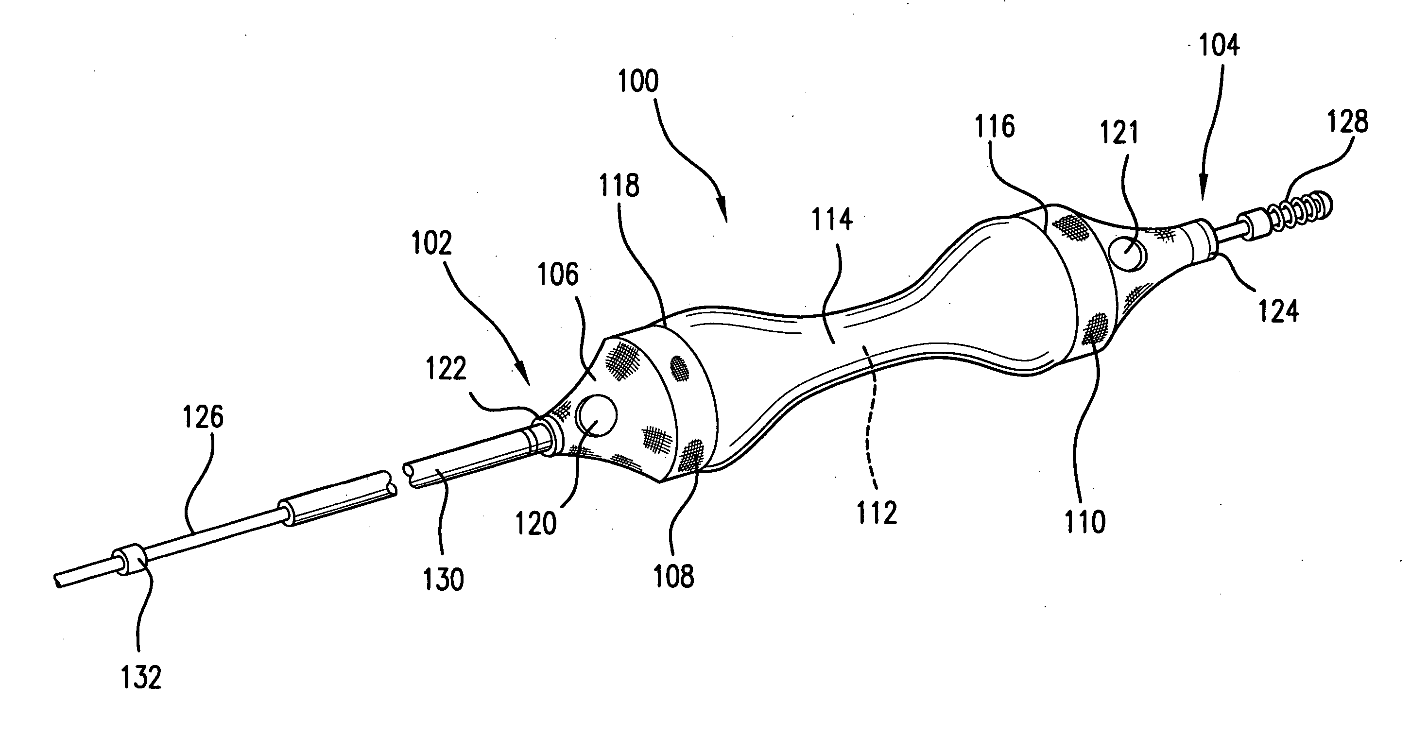
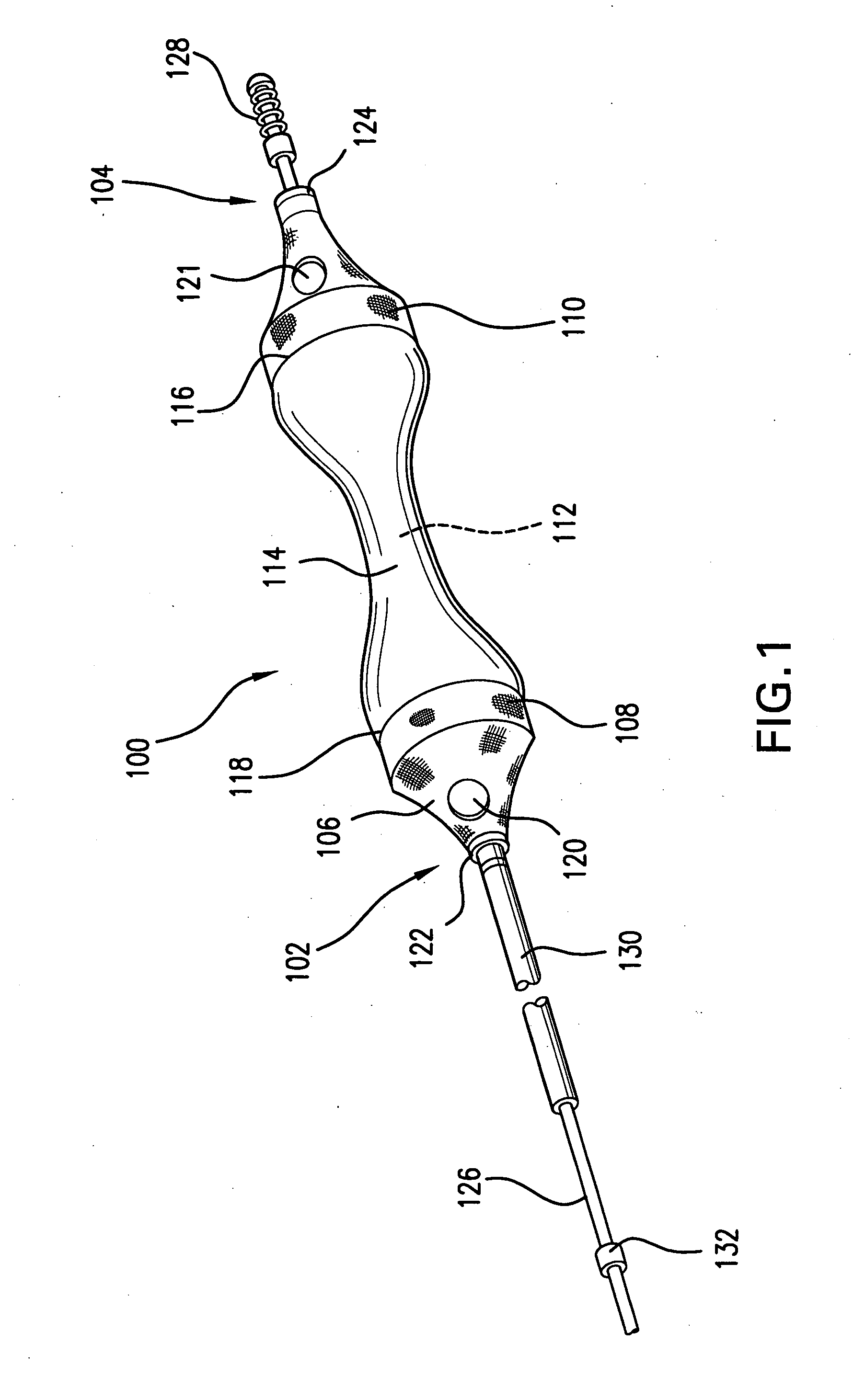
[0030] As shown in the exemplary embodiment of FIG. 1, the present invention includes a generally tubular vessel isolation device, indicated generally by reference numeral 100, mounted upon a delivery means, a guidewire 126 in the illustrated embodiment. It shall be understood that the delivery means is not limited to a guidewire. For example, a catheter tube may be used as a delivery means as ...


PUM


Abstract

The device utilizes a reversible body partially covered by a blood impermeable sleeve. The device has a low profile collapsed state for delivery and a expanded state for deployment. The impermeable sleeve extends from a proximal portion to a distal portion of the expandable body and generally follows the contour of the expandable body. When deployed, the device is configured in the expanded state and has a generally hourglass, or dumbbell shape. In the expanded state, portions of the sleeve adjacent to the proximal and distal portions are placed in apposition to a vessel wall and blood is free to flow through the expandable body via inlets and outlets provided in the proximal and distal portions. As a result, an isolated treatment space is created that surrounds the device between the vessel wall and the blood impermeable sleeve adjacent to the neck portion of the expandable body.

Description

FIELD OF THE INVENTION [0001] The present invention relates to devices used for the treatment of vascular abnormalities. In particular, the present invention relates to devices used to isolate a portion of a vessel for localized treatment of that portion of the vessel. BACKGROUND OF THE INVENTION [0002] There are many different vascular abnormalities that require medical treatment. One of the more commonly treated abnormalities is a vascular aneurysm. Vascular aneurysms are abnormal enlargements of a blood vessel that may result from disease or genetic predisposition. Aneurysms may occur in any blood vessel, but many of them occur in the abdominal aorta. If left untreated, aneurysms may rupture leading to almost certain fatality. [0003] Aneurysms are commonly treated by either bypassing the affected portion or filling the aneurysm. A bypass procedure involves the implantation of an artificial vascular graft with one end upstream of the aneurysm and a second end downstream of the ane...

Claims


Application Information

Patent Timeline
Patent Type & Authority Applications(United States)
IPC IPC(8): A61M29/00
CPCA61B17/12036A61B17/12045A61B2017/12127A61B17/12136A61B17/12172A61B17/12118
Inventor HORRIGAN, JOHN B.
Owner MEDTRONIC VASCULAR INC
Why Eureka
Try Eureka